Spiral-flow type micro bubble generator and micro bubble generation method
A microbubble generator and swirl flow technology, applied in chemical instruments and methods, mixing methods, fluid mixers, etc., can solve the problems of uneven size and distribution of microbubbles, and achieve convenient size and quantity control, Simple structure and the effect of preventing clogging
- Summary
- Abstract
- Description
- Claims
- Application Information
AI Technical Summary
Problems solved by technology
Method used
Image

Examples
Embodiment 1
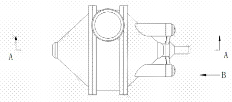
[0045] Example 1: Such as Figure 1-8 As shown, a swirling flow type microbubble generator includes three structures, namely a self-aspirating structure, a non-self-aspirating structure, and a mixed-flow structure.
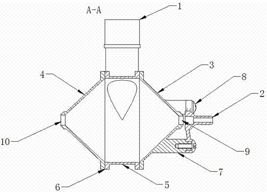
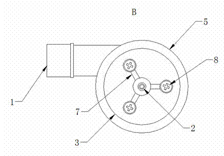
[0046] Both the self-aspirating structure and the non-self-aspirating structure include the inlet 1, the air inlet bracket 2, the conical cavity I3, the conical cavity II4, the connecting ring 5, the rubber gasket 6, and the boss bracket 7 , Screw 8, small hole 9, outlet 10; one end of the inlet 1 is connected to the pump, the other end of the inlet 1 is tangent to the circular connecting ring 5, and the threads on both sides of the connecting ring 5 are connected to the cone Conical cavity Ⅰ3 and conical cavity Ⅱ4 are connected. The connecting part where connecting ring 5 is connected with conical cavity Ⅰ3 and conical cavity Ⅱ4 is provided with rubber gasket 6, and the cavity wall of conical cavity Ⅰ3 is evenly provided with three protrusions. The table bracket 7, ...
Embodiment 2
[0062] Example 2: Such as Figure 1-8 As shown, a swirling type microbubble generator has a self-aspirating structure or a non-self-aspirating structure.
[0063] Both the self-aspirating structure and the non-self-aspirating structure include the inlet 1, the air inlet bracket 2, the conical cavity I3, the conical cavity II4, the connecting ring 5, the rubber gasket 6, and the boss bracket 7 , Screw 8, small hole 9, outlet 10; one end of the inlet 1 is connected to the pump, the other end of the inlet 1 is tangent to the circular connecting ring 5, and the threads on both sides of the connecting ring 5 are connected to the cone Conical cavity Ⅰ3 and conical cavity Ⅱ4 are connected. The connecting part where connecting ring 5 is connected with conical cavity Ⅰ3 and conical cavity Ⅱ4 is provided with rubber gasket 6, and the cavity wall of conical cavity Ⅰ3 is evenly provided with three protrusions. The table bracket 7, the three boss brackets 7 are connected to the air inlet brac...
Embodiment 3
[0073] Example 3: Such as Figure 1-8 As shown, a swirling flow microbubble generator has a mixed flow structure.
[0074] The mixed-flow structure includes an inlet 1, a cone-shaped cavity I3, a cone-shaped cavity II4, a connecting ring 5, a rubber gasket 6, a small hole 9, and an outlet 10; one end of the inlet 1 is connected to the pump, and the inlet The other end of the port 1 is tangent to the circular connecting ring 5. The threads provided on both sides of the connecting ring 5 are respectively connected to the tapered cavity I3 and the tapered cavity II4, and the connecting ring 5 is connected to the tapered cavity I3 and cone The connection part of the cavity II4 is provided with a rubber gasket 6, a small hole 9 is provided on one side of the conical cavity I3, and an outlet 10 is provided on one side of the conical cavity II4.
[0075] The apertures of the small holes 9 and the outflow port 10 are the same; among them, the apertures of the small holes 9 and the outflow ...
PUM
 Abstract
Description
Claims
Application Information
 - R&D
- Intellectual Property
- Life Sciences
- Materials
- Tech Scout
- Unparalleled Data Quality
- Higher Quality Content
- 60% Fewer Hallucinations
Browse by: Latest US Patents, China's latest patents, Technical Efficacy Thesaurus, Application Domain, Technology Topic, Popular Technical Reports.
© 2025 PatSnap. All rights reserved.Legal|Privacy policy|Modern Slavery Act Transparency Statement|Sitemap|About US| Contact US: help@patsnap.com