
Nondestructive ceramic detection device and detection method thereof

A technology of non-destructive testing and testing methods, applied in the direction of measuring devices, material analysis through optical means, instruments, etc., can solve the problems of insufficiently advanced testing methods, limited testing range, and complicated testing process, so as to prevent manual testing errors and detect The process is simple and fast, and the test results are accurate

Inactive Publication Date: 2014-10-22
SHENYANG INST OF AUTOMATION GUANGZHOU CHINESE ACAD OF SCI +1
View PDF10 Cites 67 Cited by
  • Summary
  • Abstract
  • Description
  • Claims
  • Application Information

AI Technical Summary

Problems solved by technology

Disadvantages of this equipment: 1. The structure of the equipment is complex, prone to failure and difficult to maintain; 2. The detection process is complicated and the efficiency is relatively low; 3. The detection method is not advanced enough, so that the detection results are not accurate enough; 4. The detection process The production line has pauses and is prone to mechanical damage; 5. One station only completes part of the surface quality inspection items, and the functions are not complete
The disadvantages of this equipment: 1. The structure of the equipment is complicated, it is prone to failure, and maintenance is also difficult; 2. The products that have been detected need to be manually classified; 3. The equipment needs to be stopped for detection, and the detection efficiency is relatively low; 4. The detection range is relatively small. Limitation, only the edge of the ceramic plate can be detected; 5. The use of double conveyor belts is easy to cause asynchrony, which will cause relative displacement and cause detection errors; 6. Cannot complete edge straightness detection and color number detection

Method used


Image

  • Nondestructive ceramic detection device and detection method thereof
  • Nondestructive ceramic detection device and detection method thereof
  • Nondestructive ceramic detection device and detection method thereof

Examples


Embodiment

[0041] This embodiment provides nondestructive testing equipment for ceramic tiles. The nondestructive testing equipment for ceramic tiles is mainly composed of a control system, a detection system, and a motion system, wherein the control system is composed of a host computer, an operation interface, and a control box. Sensors, linear light sources, and motion systems are composed of motors, conveyor belts, timing belts, and encoders.

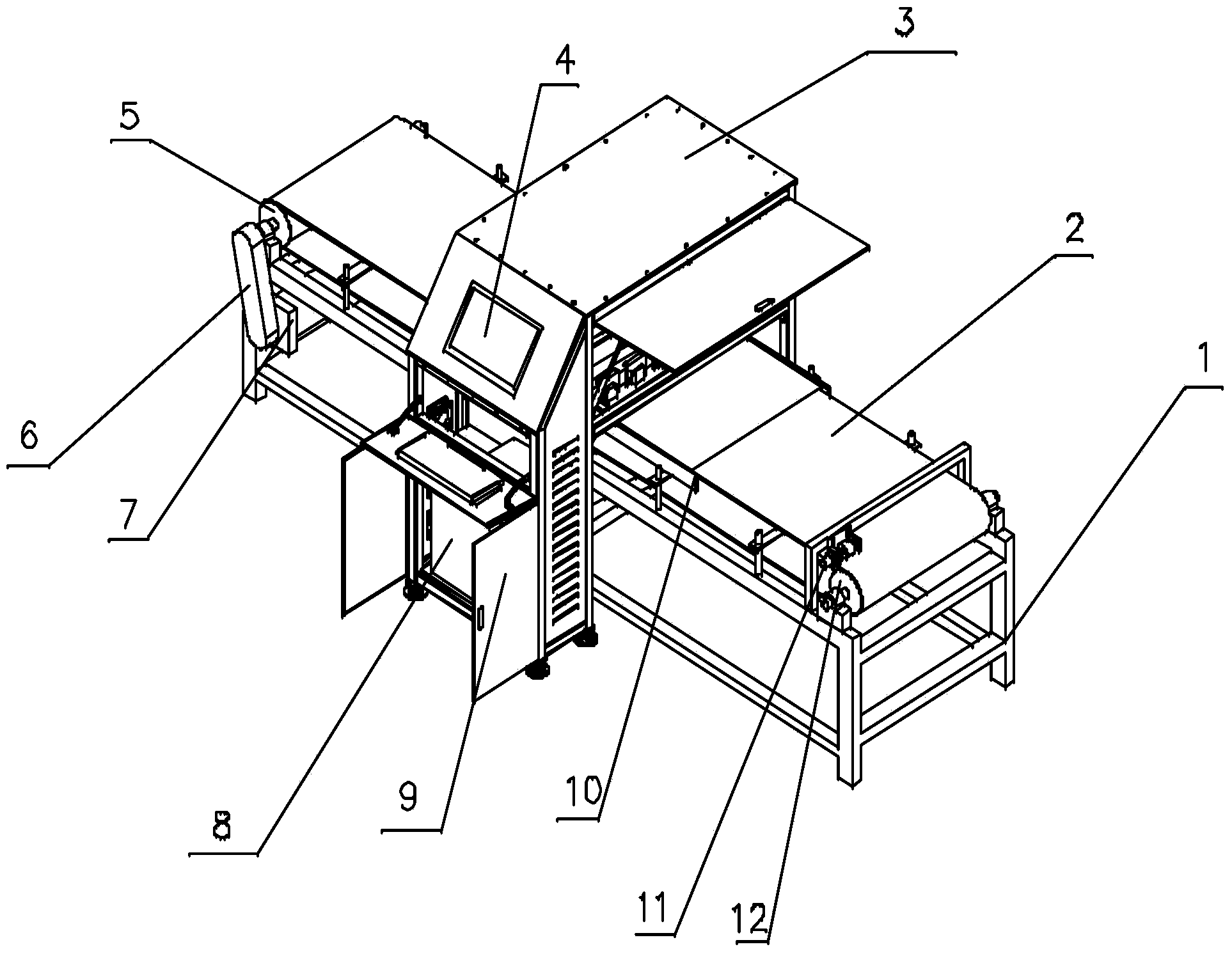
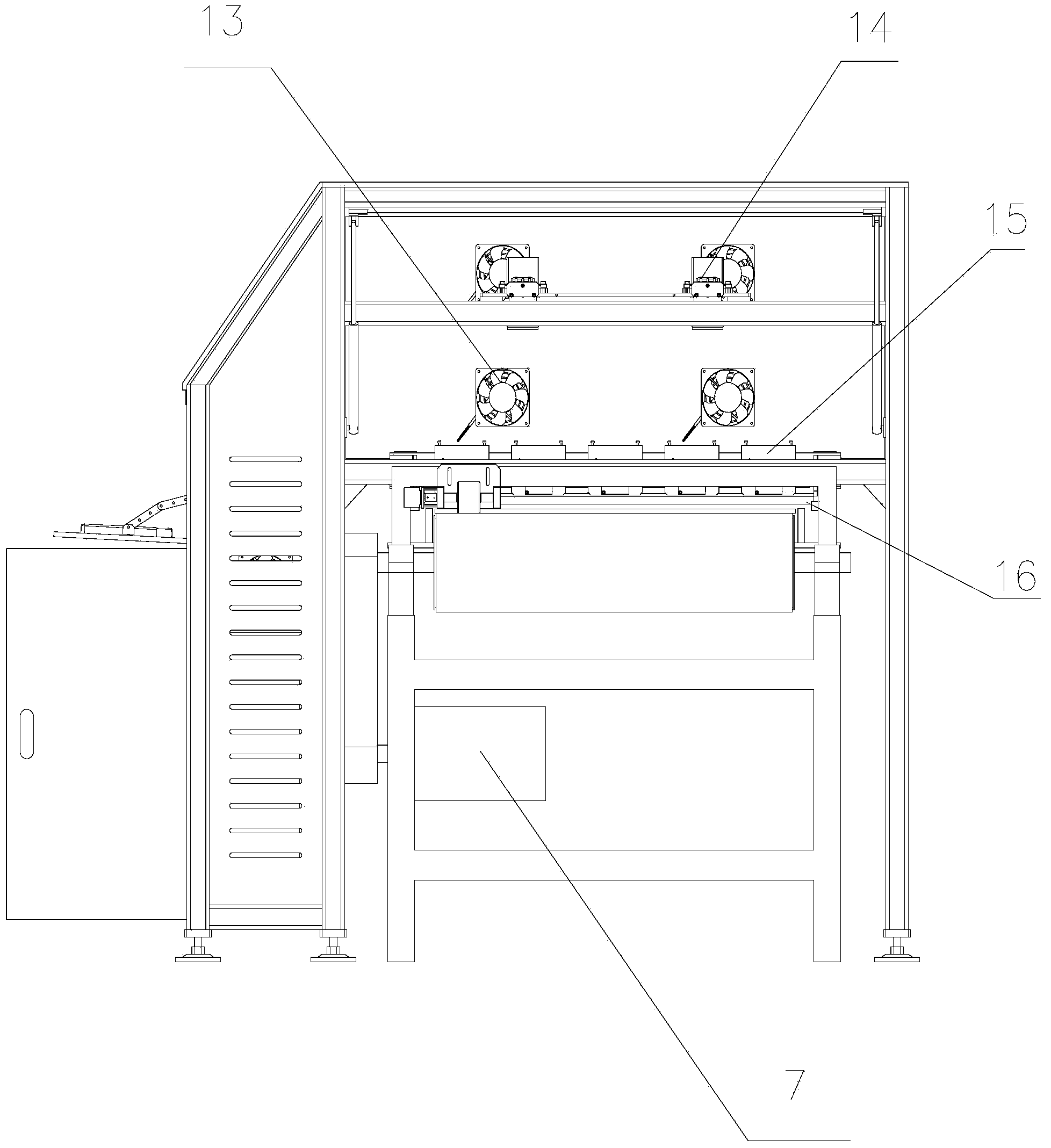
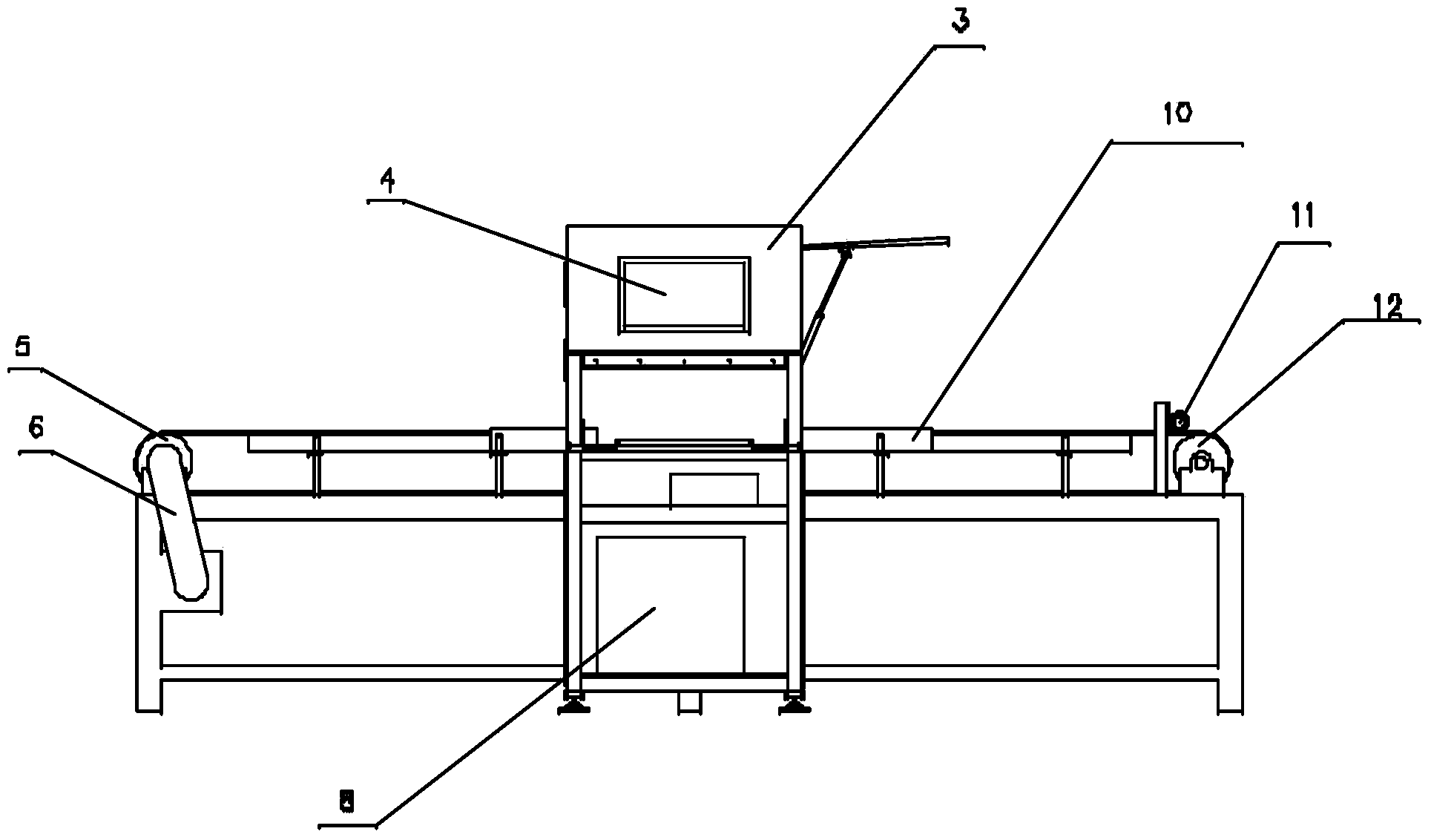
[0042] Such as figure 1 , figure 2 , image 3As shown, the nondestructive testing equipment for ceramic tiles in this embodiment includes a frame 1, a conveyor belt 2, a machine cover 3, an operation interface 4, a driving wheel 5, a timing belt 6, a motor 7, a detection host 8, a control box 9, a positioning Baffle 10 , encoder 11 , driven wheel 12 , fan 13 , linear CCD camera 14 , laser displacement sensor 15 and linear light source 16 .

[0043] The frame 1 is a rectangular parallelepiped frame, and the bottom of the rectangular paralle...


PUM


Abstract

The invention discloses a nondestructive ceramic detection device and a detection method thereof. The detection device comprises a rack and an engine cover, wherein the engine cover stretches across the middle of the rack in a portal frame mode; a driving wheel and a driven wheel are respectively mounted at two ends of the rack; a motor is arranged on a framework on one side of the rack; the driving wheel is connected with the motor through a synchronous belt; a fan is mounted on one transverse side of the engine cover; a control cabinet is mounted on one vertical side of the engine cover; the lower half part of the control cabinet is of cabinet type; a detection host is arranged in the cabinet; a linear CCD (Charge Coupled Device) camera is arranged on a first cross beam in the engine cover; a linear light source is arranged under the linear CCD camera; a plurality of laser displacement sensors are arranged on a second cross beam of the engine cover. The detection device is simple in structure, convenient to maintain and capable of effectively avoiding artificial detection error; meanwhile, according to the detection method, the detection process is simple and quick, the detection result is accurate and the detection efficiency is high.

Description

technical field [0001] The invention relates to the field of ceramic production testing equipment manufacturing, in particular to a ceramic brick non-destructive testing equipment and a testing method capable of quickly and accurately testing the technical parameters of the ceramic bricks to be checked. Background technique [0002] In the existing ceramic tile production line, most of the inspection process of ceramic tiles is to send the tested ceramic tiles to the inspection box, and use the detection device to detect the surface of the ceramic tiles. Through data collection and comparison, the final result is Test results. In this process, professionals are required to monitor it, so there are many subjective influencing factors. The detection efficiency and stability of this equipment cannot adapt to today's large-scale ceramic tile production lines. [0003] Chinese invention patent (authorized announcement number is CN101169452B) discloses a kind of ceramic tile qual...

Claims


Application Information

Patent Timeline
IPC IPC(8): G01N21/892G01B11/00B07C5/342
Inventor 刘洪江刘和惠沙亚红王文洪李振伟黄敦新
Owner SHENYANG INST OF AUTOMATION GUANGZHOU CHINESE ACAD OF SCI
Learn More