
Wear-resistant spiral blade for concrete mixing tank

A technology of helical blades and mixing tanks, which is applied in the field of wear-resistant helical blades of concrete mixing tanks, and can solve the problems of poor mixing, feeding and unloading performance of mixing tanks, poor performance of feeding and discharging materials and mixing of mixing tanks, and easy breakage of blade welding and other problems, to achieve the effect of smooth feeding and discharging, improved stirring performance, and firm welding

Inactive Publication Date: 2014-10-22
GUANGXI KELIANG ROAD & BRIDGE MACHINERY
View PDF9 Cites 3 Cited by
  • Summary
  • Abstract
  • Description
  • Claims
  • Application Information

AI Technical Summary

Problems solved by technology

[0002] The existing concrete mixing tank needs to be continuously stirred by the spiral blade when loading concrete, and at the same time, the feeding and unloading functions are completed by using the transmission principle of the spiral blade. Since the blade is often subjected to friction and impact of concrete, the blade is extremely prone to wear, or The welding part of the blade is prone to breakage, which will cause the performance of mixing, feeding and unloading of the mixing tank to decrease, and the service life will be reduced
[0003] In addition, at present, most of the spiral blades of the mixing tank do not have a curved surface structure, and are mainly rotated and twisted according to the direction of the helix. Poor, failed to meet the needs of the market well

Method used


Image

  • Wear-resistant spiral blade for concrete mixing tank
  • Wear-resistant spiral blade for concrete mixing tank
  • Wear-resistant spiral blade for concrete mixing tank

Examples


Embodiment Construction

[0022] The following combination figure 1 , figure 2 , image 3 Specific embodiments of the present invention will be described in detail.

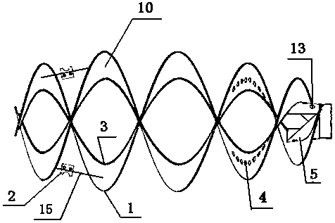
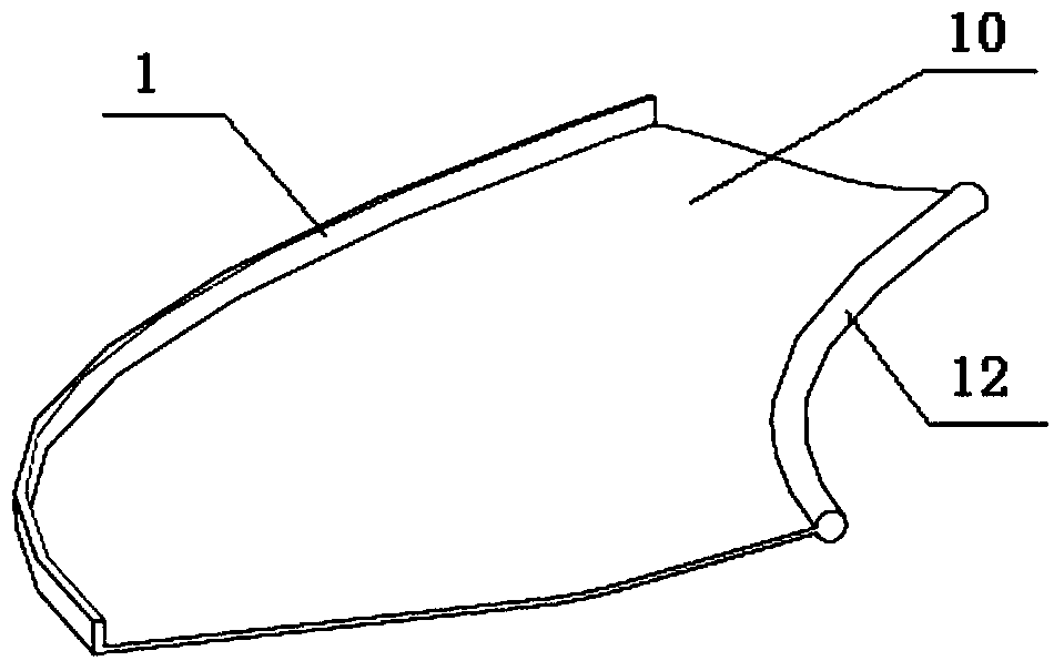
[0023] A wear-resistant helical blade for a concrete mixing tank. The tank body is divided into a front cone 7, a middle cylinder 8, and a rear cone 9. A pair of helical blades 10 adopts a non-equal angle logarithmic helix design with different pitches and helical angles. It is uniquely concave and realizes the three-dimensional mixing function; a pair of mixing blades 2 are arranged at the place where the inner pitch of the front cone 7 is relatively large. Two adjacent blades 10; a central cylinder 5 is provided in the rear cone 9, one end of the central cylinder 5 is straight and fixedly connected to the tank mouth 14, and the other end is a notch horn shape, and different numbers of through holes 13 are arranged on the horn surface. Conducive to smooth feeding, the end of the blade 10 is welded on the outer wall of the central cyl...


PUM


Abstract

The invention discloses wear-resistant spiral blades for a concrete mixing tank. A tank body is divided into a front cone, a middle cylinder and a rear cone. A pair of spiral blades are designed in an isometric logarithmic spiral line; both thread pitch and spiral angles are different; cross sections of the spiral blades are in a unique concave shape to realize a three-dimensional mixing function; the front cone is provided with mixing blades; the mixing blades are fixed on the rod member in a manner of smaller than the spiral angle of the blade; two ends of a rod member are connected to two adjacent blades respectively; the rear cone is provided with a central cylinder; one end of the central cylinder is in a straight tube shape and fixedly connected to a tank opening; the other end of the central cylinder is in a notched horn shape; the horn surface is provided with through holes in different apertures, so as to facilitate smooth material feeding; the tail end of the blade is fixedly connected to an outer wall of the central cylinder; an inner wall of the tank opening of the rear cone is fixedly connected to a streamlined auxiliary vane for accelerating material-discharging speed and material-discharging shunting effect. The blades provided by the invention have the three-dimensional mixing function, have good mixing performance, are fast and smooth in material feeding and discharging, are firm and wear-resistant, and prolong a service life.

Description

technical field [0001] The invention belongs to the technical field of concrete mixer trucks, and in particular relates to a wear-resistant spiral blade of a concrete mixer tank. Background technique [0002] The existing concrete mixing tank needs to be continuously stirred by the spiral blade when loading concrete, and at the same time, the feeding and unloading functions are completed by using the transmission principle of the spiral blade. Since the blade is often subjected to friction and impact of concrete, the blade is extremely prone to wear, or The welding part of the blade is prone to breakage, which will cause the performance of stirring, feeding and unloading of the mixing tank to decrease, and the service life will be reduced. [0003] In addition, at present, most of the spiral blades of the mixing tank do not have a curved surface structure, and are mainly rotated and twisted according to the direction of the helix. Poor, failed to meet the needs of the marke...

Claims


Application Information

Patent Timeline
IPC IPC(8): B28C5/08
CPCB28C5/4268B28C5/1868
Inventor 廖柏淞
Owner GUANGXI KELIANG ROAD & BRIDGE MACHINERY
Learn More