


Quick Research
Generate reliable direction feasibility study reports for your R&D in just a few steps.

Technical Q&A
Discover and master advanced knowledge NOW. Basics, ideas, possibilities, all at once.

Find Solutions
As an expert in R&D theories, this can generate solutions to your technical problems instantly.

Evaluate Feasibility
Analyze your overall solution with one click, know your potential R&D risks in advance.

Monitor Landscape
Get weekly tech updates, stay abreast of the latest tech innovations and key insights.
Reference voltage generating circuit
A reference voltage and generation circuit technology, applied in the direction of adjusting electrical variables, control/regulating systems, instruments, etc., can solve the problems of limiting the performance of the bandgap reference source, high output noise of the bandgap reference, and large current consumption. The effect of small layout area, high PSRR, and low power consumption
- Summary
- Abstract
- Description
- Claims
- Application Information
AI Technical Summary
Problems solved by technology
Method used
Image

Examples
specific Embodiment 1
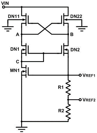
[0027] like figure 1 The shown reference voltage generation circuit includes: a pre-adjustment circuit that converts an input voltage into a pre-regulated voltage, and a core circuit that generates a reference voltage under the action of the pre-regulated voltage. The pre-adjustment circuit includes: depletion-type NMOS transistor DN11, depletion-type NMOS transistor DN22. The core circuit includes: depletion NMOS transistor DN1, depletion NMOS transistor DN2, enhanced NMOS transistor MN1, and resistor R1. The drains of the depletion-type NMOS transistors DN11 and DN22 are both connected to the input voltage VIN, the substrates of the depletion-type NMOS transistors DN11 and DN22 are both grounded, the source of the depletion-type MOS transistor DN11 and the gate of the depletion-type NMOS transistor DN22 are connected to the The depletion mode NMOS transistor DN1 drain connection ( figure 1 point A in), the source of the depletion-type NMOS transistor DN22, the gate of the ...
specific Embodiment 2
[0033] On the basis of the specific embodiment 1, the voltage division branch is introduced, and the voltage division branch can be figure 1 The resistor R2 shown, the resistor R1 and the resistor R2 are connected in series to form a voltage divider circuit, for V REF1 voltage divider can be obtained below V REF1 value of any reference voltage V REF2 , V REF2 =V REF1 *R2 / (R1+R2). Various implementations can be selected for the voltage-dividing branch according to the requirements of the reference voltage, and each voltage-dividing output point of the voltage-dividing circuit is used as an output point of any reference voltage. This example realizes the output of any value reference voltage.
specific Embodiment 3
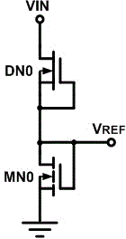
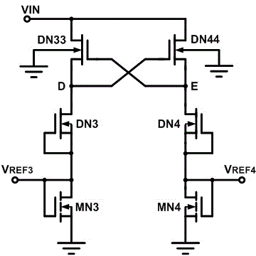
[0034] figure 2 with the reference voltage generating circuit shown in 3. V REF The value is a fixed value, and it cannot provide other slightly lower arbitrary value reference voltages, and it is difficult to perform Trimming to increase V REF accuracy. If the resistor trimming function is added to the resistor R1 or R2, the size of resistor R1 and resistor R2 can be increased by laser or aluminum burning REF2 Accuracy, eliminating the V REF1 value deviation.
PUM
 Abstract
Description
Claims
Application Information
 - R&D Engineer
- R&D Manager
- IP Professional
- Industry Leading Data Capabilities
- Powerful AI technology
- Patent DNA Extraction
Browse by: Latest US Patents, China's latest patents, Technical Efficacy Thesaurus, Application Domain, Technology Topic, Popular Technical Reports.
© 2024 PatSnap. All rights reserved.Legal|Privacy policy|Modern Slavery Act Transparency Statement|Sitemap|About US| Contact US: help@patsnap.com