
Acceleration type linear magnetic gear permanent magnet composite motor

A composite motor and permanent magnet motor technology, applied in the direction of belts/chains/gears, electromechanical devices, electrical components, etc., can solve the problems of low wave motion speed, reduced power density, low power density, etc., to achieve high power density, reduce The effect of small size and simplified manufacturing process

Inactive Publication Date: 2014-10-08
SOUTHEAST UNIV
View PDF3 Cites 8 Cited by
  • Summary
  • Abstract
  • Description
  • Claims
  • Application Information

AI Technical Summary

Problems solved by technology

Rotary power generation systems inevitably require complex mechanical devices, such as water turbines or hydraulic pumps, to convert linear reciprocating wave motion into rotary motion, so rotating electrical machines have the following problems: routine maintenance, low efficiency, low power density, high cost
However, the wave motion speed is low, and the direct-drive linear generator needs to be designed at a low speed, which greatly reduces its power density

Method used


Image

  • Acceleration type linear magnetic gear permanent magnet composite motor
  • Acceleration type linear magnetic gear permanent magnet composite motor

Examples


Embodiment Construction

[0021] The present invention will be further described below in conjunction with the accompanying drawings.

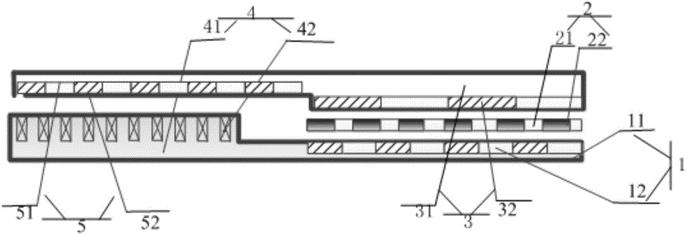
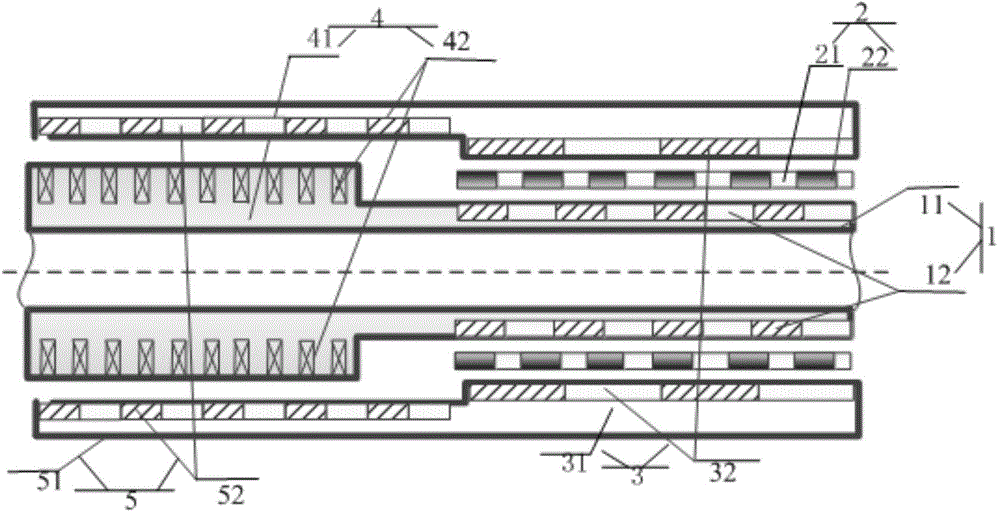
[0022] Such as figure 1 , figure 2 Shown is a speed-increasing linear magnetic gear permanent magnet composite motor, including two parts: a linear magnetic gear and a linear permanent magnet synchronous motor. The two parts are connected along the length direction and coupled in series; the two parts will be described in detail below.

[0023] The linear magnetic gear part includes a magnetic gear stator 1, a magnetic regulating sheet 2 and a magnetic gear high-speed mover 3; the magnetic gear stator 1 includes a magnetic gear stator core 11, and a magnetic gear stator is embedded in the tooth slot of the magnetic gear stator core 11 The permanent magnet 12; the magnetism regulating sheet 2 includes the magnetism regulating sheet non-magnetizer 21 and the magnetism regulating sheet magnetizer 22 arranged at staggered intervals along the length direction; the magneti...


PUM


Abstract

The invention discloses an acceleration type linear magnetic gear permanent magnet composite motor which comprises a linear magnetic gear and a linear permanent magnet synchronous motor. The linear magnetic gear and the linear permanent magnet synchronous motor are connected in the length direction in series and coupled. The linear magnetic gear comprises a magnetic gear stator, a magnetic modulation sheet and a magnetic gear high-speed rotor. The magnetic modulation sheet is arranged between the magnetic gear stator and the magnetic gear high-speed rotor. A first air gap is formed between the magnetic gear stator and the magnetic modulation sheet. A second air gas is formed between the magnetic modulation sheet and the magnetic gear high-speed rotor. The linear permanent magnet synchronous motor comprises a primary linear permanent magnet motor and a secondary linear permanent magnet motor. A third air gap is formed between the primary linear permanent magnet motor and the secondary linear permanent magnet motor. A magnetic gear stator iron core and a primary iron core are connected in series, coupled and kept to be fixed. According to the structure of the acceleration type linear magnetic gear permanent magnet composite motor, a motor magnetic field is modulated through a magnetic modulation iron core ring, non-contact-type speed changing and thrust transmission are achieved, contact losses are reduced, the power density of the motor is improved, the system size and weight are reduced, and the manufacturing cost is reduced.

Description

technical field [0001] The invention relates to a speed-increasing linear magnetic gear permanent magnet composite motor, which is also used in a direct-drive wave power generation system. Background technique [0002] In the development and utilization of renewable energy, wave energy has a bright future, but the technology is still immature. A major problem is the lack of generators that efficiently harness wave energy. Rotary power generation systems inevitably require complex mechanical devices, such as water turbines or hydraulic pumps, to convert linear reciprocating wave motion into rotary motion, so rotating electrical machines have the following problems: routine maintenance, low efficiency, low power density, high cost. The linear power generation system uses the linear motor to directly utilize the wave motion, eliminating the bulky linear-rotary transmission and the resulting power loss. However, the wave motion speed is low, and the direct-drive linear genera...

Claims


Application Information

Patent Timeline
Patent Type & Authority Applications(China)
IPC IPC(8): H02K41/02H02K41/03H02K1/27F16H49/00H02K7/10H02K7/18
Inventor 余海涛封宁君
Owner SOUTHEAST UNIV
Learn More