
Method for detecting self safety of polyurethane grouting reinforcement material for underground coal mine in use process

A technology of grouting reinforcement and detection method, which is applied in the field of detecting whether the polyurethane grouting reinforcement material will smolder when it is used in underground coal mines, so as to achieve the effect of ensuring its own safety and the method is simple and fast

Inactive Publication Date: 2014-10-08
HEFEI UNIV OF TECH
View PDF5 Cites 5 Cited by
  • Summary
  • Abstract
  • Description
  • Claims
  • Application Information

AI Technical Summary

Problems solved by technology

[0004] However, there is currently no way to detect whether polyurethane grouting reinforcement materials will produce smoldering phenomena when used underground in coal mines

Method used


Image

  • Method for detecting self safety of polyurethane grouting reinforcement material for underground coal mine in use process
  • Method for detecting self safety of polyurethane grouting reinforcement material for underground coal mine in use process
  • Method for detecting self safety of polyurethane grouting reinforcement material for underground coal mine in use process

Examples


Embodiment 1

[0061] The formula of the polyurethane grouting reinforcement material to be tested that this embodiment selects is:

[0062] Component A:

[0063] Component B: Polyisocyanate PAPI 110 parts

[0064] This embodiment takes the polyurethane grouting reinforcement material as an example to illustrate the detection method of the present invention, and the specific steps are as follows:

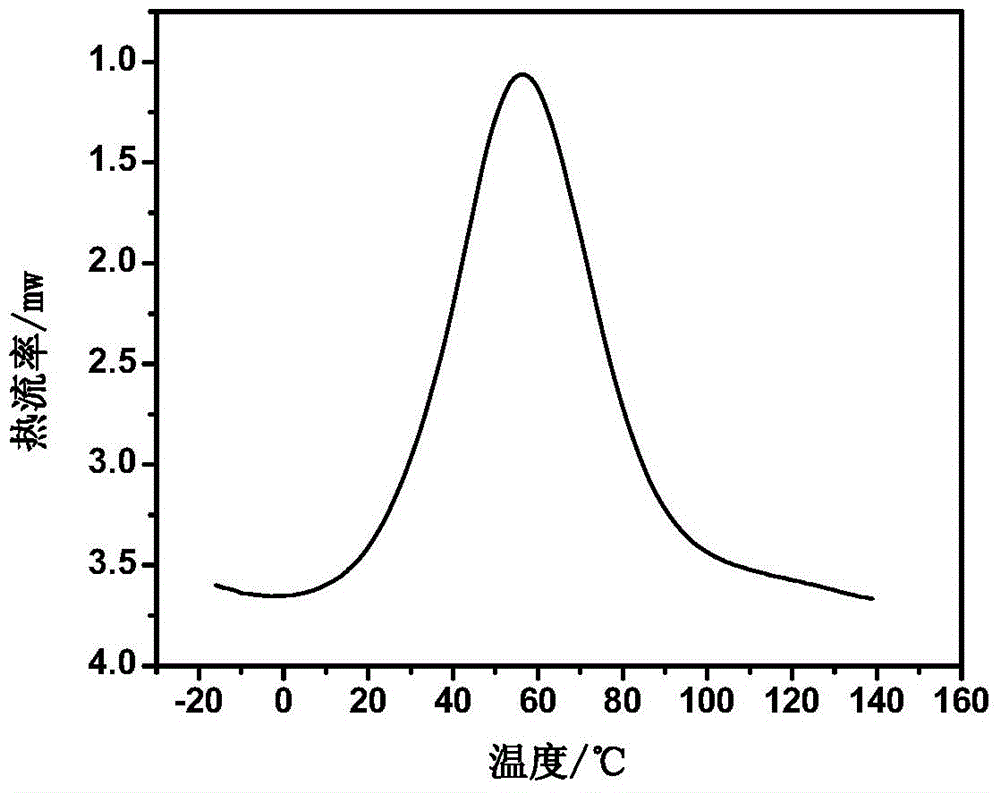
[0065] 1. Determination of the theoretical maximum reaction temperature T of the polyurethane grouting reinforcement material during the curing process max :

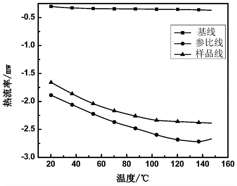
[0066] a. Differential scanning calorimeter (DSC) indirect method to test the specific heat capacity C of polyurethane grouting reinforcement material p :

[0067] a1. Select two empty crucibles, one of which is pressed and sealed as a reference plate, and the other set is covered but not sealed as a sample plate and put into the DSC;

[0068] a2. Set up and run the following program: raise the temperature from 20°C to 150°C at a hea...

Embodiment 2

[0085] The formula of the polyurethane grouting reinforcement material to be tested that this embodiment selects is:

[0086] Component A:

[0087] Component B: polyisocyanate PAPI 71 parts

[0088] This embodiment takes the polyurethane grouting reinforcement material as an example to illustrate the detection method of the present invention, and the specific steps are as follows:

[0089] 1. Determination of the theoretical maximum reaction temperature T of the polyurethane grouting reinforcement material during the curing process max :

[0090] a. Differential scanning calorimeter (DSC) indirect method to test the specific heat capacity C of polyurethane grouting reinforcement material p :

[0091] a1. Select two empty crucibles, one of which is pressed and sealed as a reference plate, and the other set is covered but not sealed as a sample plate and put into the DSC;

[0092] a2. Set up and run the following program: raise the temperature from 20°C to 150°C at a heat...


PUM


Abstract

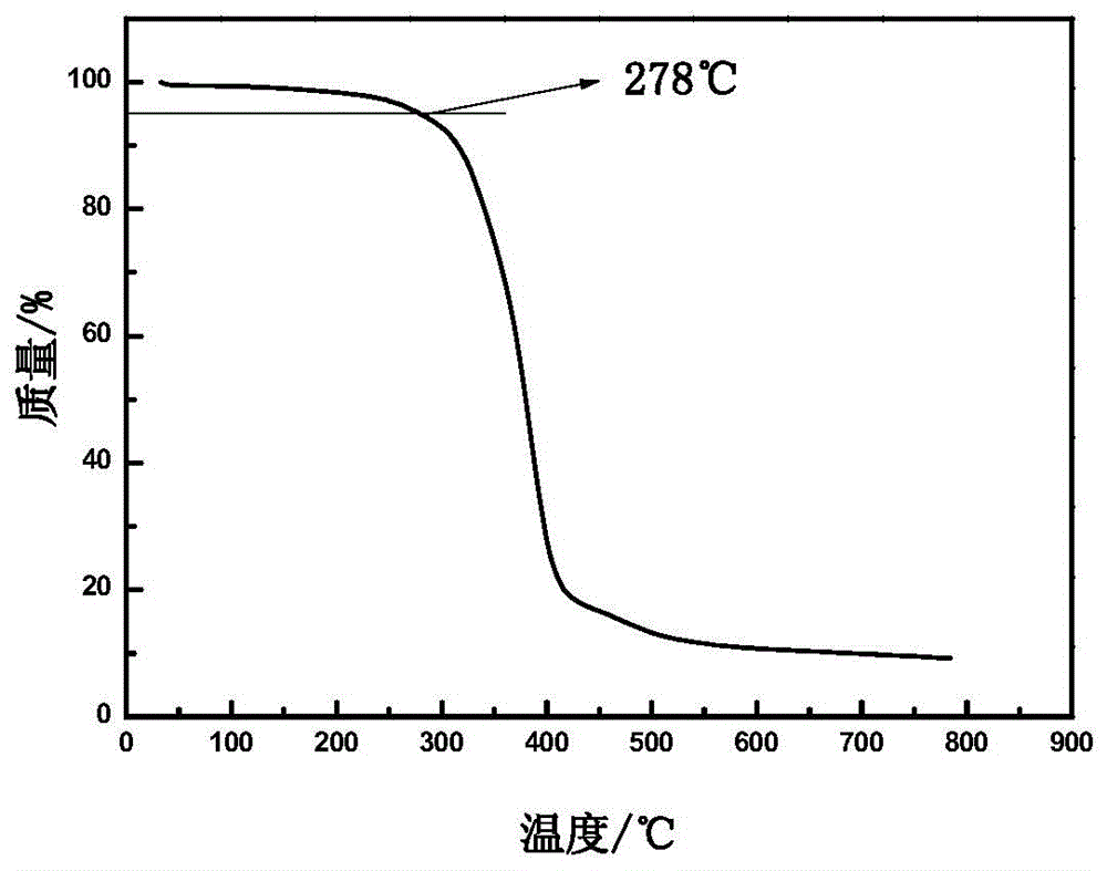
The invention discloses a method for detecting the self safety of a polyurethane grouting reinforcement material for an underground coal mine in a use process. The detection method is characterized by comprising the following steps that the polyurethane grouting reinforcement material is solidified, the theoretical highest reaction temperature during solidification and the thermal decomposition temperature after solidification of the polyurethane grouting reinforcement material are measured, and then the two temperatures are compared to judge whether the polyurethane grouting reinforcement material is safe. According to the detection method disclosed by the invention, an existing thermoanalysis technique is utilized, and the theoretical highest reaction temperature during solidification and the thermal decomposition temperature after solidification of the polyurethane grouting reinforcement material are compared to judge whether the material smolders when being used for the underground coal mine. The detection method has the advantages of simplicity and rapidity, and can be used for judging the self safety of the polyurethane grouting reinforcement material in the use process accurately and effectively.

Description

technical field [0001] The invention relates to a method for detecting self-safety of a polyurethane grouting reinforcement material used in coal mines, in particular to a detection method for detecting whether the polyurethane grouting reinforcement material will smolder when it is used underground in a coal mine. Background technique [0002] At present, about 40% of the coal mines in my country have coal-measure strata that are soft rock formations. In addition to the influence of factors such as structure and stress concentration, the rock formations are more loose, which brings great difficulties to roadway support and safe production. In recent years, the polymer grouting reinforcement technology for coal mines has attracted more and more attention. In particular, this technology can effectively control the deformation of the surrounding rock and significantly improve the support effect of the soft and broken surrounding rock roadway, which has great application prospec...

Claims


Application Information

Patent Timeline
IPC IPC(8): G01N5/04G01N25/20
Inventor 丁运生蔡明倪建明马东东刘玉亭孙晓红
Owner HEFEI UNIV OF TECH
Learn More