Method and device for dynamic weighing estimation of toll booth vehicles

A dynamic weighing and estimating device technology, applied in measuring devices, weighing, instruments, etc., can solve the problems of slow measurement, damaged road surface, slow vehicle speed, etc., and achieve the effect of improving traffic efficiency and saving time

Active Publication Date: 2016-06-29
佛山市衡王电子衡器有限公司
View PDF6 Cites 0 Cited by
  • Summary
  • Abstract
  • Description
  • Claims
  • Application Information

AI Technical Summary

Problems solved by technology

[0002] Vehicle overloading will not only damage the road surface, increase the cost of road maintenance, but also cause traffic accidents. In order to control the phenomenon of vehicle overloading, it is necessary to measure the quality of vehicles passing on the road
The traditional vehicle quality measurement method is carried out when the vehicle remains stationary. Although static weighing has high measurement accuracy, the measurement speed is slow, resulting in low efficiency of toll booths and easy to cause traffic jams.
At present, the dynamic weighing system of the highway toll station is generally used to measure the quality of passing vehicles. The dynamic weighing system is mainly composed of a weighing platform, a load cell and a weighing instrument. For the load cell, when the sensor is stressed, the axle load signal is converted into a voltage signal and transmitted to the weighing instrument, and the weight of the vehicle is displayed after the instrument processing; Fast measurement cannot be achieved well, and the force acting on the weighing platform is disturbed by other external factors besides the real axle load, thus affecting the accuracy of dynamic weighing

Method used


Image

  • Method and device for dynamic weighing estimation of toll booth vehicles
  • Method and device for dynamic weighing estimation of toll booth vehicles
  • Method and device for dynamic weighing estimation of toll booth vehicles

Examples


Embodiment Construction

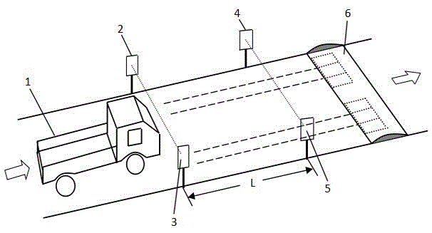
[0017] see figure 1 According to the present invention, the vehicle dynamic weighing and estimating device at the toll station includes a vehicle speed measuring module and a measuring impact force module. The vehicle speed measurement module is composed of a laser transmitter group and a photoelectric receiver group, which are respectively installed on the left and right sides of the toll station road. The laser transmitter group is composed of the first laser transmitter 2 and the second laser transmitter 4, the distance between the first laser transmitter 2 and the second laser transmitter 4 is L along the road length direction, and the photoelectric receiver group is composed of the first photoelectric receiver The device 3 is composed of the second photoelectric receiver 5, and the distance between the first photoelectric receiver 3 and the second photoelectric receiver 5 along the length direction of the road is also L. The first laser transmitter 2 is facing the first ...


PUM


Abstract

The invention discloses a method and device for dynamic weighing and estimation of vehicles at a toll station. The left and right sides of the toll station road are respectively equipped with a laser transmitter group and a photoelectric receiver group; the vehicle to be tested first blocks the laser light emitted by the first laser transmitter, and then Block the laser emitted by the second laser transmitter, the MCU control system calculates the speed of the vehicle to be measured before passing the impact force measuring device, and the left and right pressure sensor groups input the signals of the impact force of the left and right wheels into the MCU control system; The speed and impact force of the vehicle to be tested are used as the input of the BP artificial neural network model, and the mass is used as the output to estimate the vehicle mass; the present invention comprehensively considers the kinetic energy of the moving vehicle and the impact force generated during the collision with the force measuring device. Using road speed bumps to allow vehicles to maintain a certain speed passing through the speed bumps, combined with artificial neural network technology to achieve indirect measurement of vehicle quality and improve toll station traffic efficiency.

Description

technical field [0001] The invention relates to the field of vehicle weighing at toll stations, and can quickly measure the mass of vehicles passing through toll stations by estimating the mass of vehicles passing through toll stations, especially for vehicles passing through toll stations dynamically, so as to improve the traffic efficiency of toll stations. Background technique [0002] Vehicle overloading will not only damage the road surface, increase the cost of road maintenance, but also cause traffic accidents. In order to control the phenomenon of vehicle overloading, it is necessary to measure the quality of vehicles passing on the road. The traditional vehicle quality measurement method is carried out when the vehicle remains stationary. Although static weighing has high measurement accuracy, the measurement speed is relatively slow, resulting in low efficiency of toll booths and easy to cause traffic jams. At present, the dynamic weighing system of the highway tol...

Claims


Application Information

Patent Timeline
Patent Type & Authority Patents(China)
IPC IPC(8): G01G19/03
Inventor 张荣标董荣伟陈金龙
Owner 佛山市衡王电子衡器有限公司
Why Eureka
Try Eureka