
A ball mill

A ball mill and stand technology, which is applied in the field of mining machinery, can solve the problems of the main bearing at the feed end of the ball mill entering water and pulp, the deterioration of lubricating oil, and the loss of sealing effect of the oil seal.

Inactive Publication Date: 2014-10-08
GUANYANG CHENGONG ORE DRESSING MACHINERY MFG
View PDF11 Cites 4 Cited by
  • Summary
  • Abstract
  • Description
  • Claims
  • Application Information

AI Technical Summary

Problems solved by technology

However, in the production process of the existing ball mill, the phenomenon that the main bearing at the feed end of the ball mill often enters water and pulp, causing the oil seal to lose its sealing effect, the lubricating oil to deteriorate, and finally damage the shaft and bearing; Noise is generated in the middle, the speed cannot be adjusted, or it is turned over, and the effect of crushing ore is not good

Method used


Image

  • A ball mill

Examples


Embodiment Construction

[0016] The principles and features of the present invention are described below in conjunction with the accompanying drawings, and the examples given are only used to explain the present invention, and are not intended to limit the scope of the present invention.

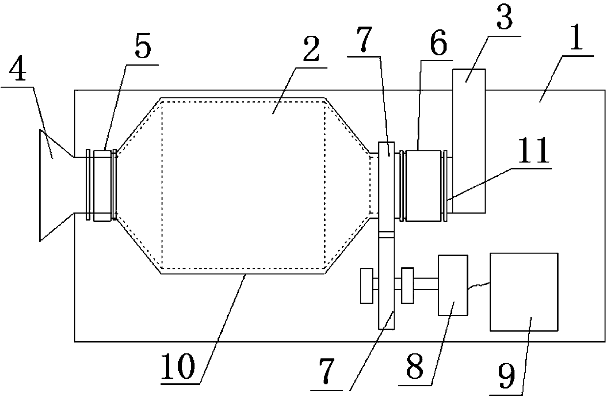
[0017] Such as figure 1 As shown, a ball mill includes a machine base 1, a cylinder body 2, a feed pipe 3, a discharge port 4, bearing seats 5, 6, a gear 7, a motor 8 and a PLC control box 9, and the cylinder body 2 is placed in Above the base 1, the bearing blocks 5, 6 include a first bearing block 5 and a second bearing block 6, the bottoms of the first bearing block 5 and the second bearing block 6 are fixed on the frame 1, and the top Placed at both ends of the cylinder body 2 respectively, the discharge port 4 is connected to one end of the cylinder body 2 through the first bearing seat 5, and the feed pipe 3 is connected to the other end of the cylinder body 2 through the second bearing seat 6 connection, the...


PUM


Abstract

The invention relates to a ball mill. The ball mill comprises a pedestal, a cylinder, a feeding pipe, a discharging port, bearing pedestals, gears, a motor and a PLC control cabinet. The cylinder is disposed on the pedestal. The bearing pedestals comprise a first bearing pedestal and a second bearing pedestal. The bottoms of the first and second bearing pedestals are fixed to the pedestal. The tops of the first and second bearing pedestals are respectively disposed at two ends of the cylinder. The discharging port passes through the first bearing pedestal and is connected to one end of the cylinder. The feeding pipe passes through the second bearing pedestal and is connected to the other end of the cylinder. The number of the gears is two. One of the gears sleeves one end of the cylinder and is fixedly connected to the cylinder, and the other gear is fixedly connected to the output shaft of the motor. The two gears are meshed in cooperation with each other. The motor is connected to the PLC control cabinet through a circuit. Compared with the prior art, the ball mill is capable of reducing running noise, clearing water and ore slurry next to the bearing pedestals and controlling the running speed.

Description

technical field [0001] The invention relates to the technical field of mineral machinery, in particular to a ball mill. Background technique [0002] The ball mill is the key equipment for crushing the material after it is crushed. It is widely used in cement, silicate products, refractory materials, chemical fertilizers, black and non-ferrous metal beneficiation and glass ceramics and other production industries. Existing ball mills generally consist of a ball mill cylinder and a transmission device connected to the ball mill cylinder. However, in the production process of the existing ball mill, the phenomenon that the main bearing at the feed end of the ball mill often enters water and pulp, causing the oil seal to lose its sealing effect, the lubricating oil to deteriorate, and finally damage the shaft and bearing; Noise is generated in the middle, the speed cannot be adjusted, or it is turned over, and the effect of crushing ore is not good. Contents of the inventio...

Claims


Application Information

Patent Timeline
Patent Type & Authority Applications(China)
IPC IPC(8): B02C17/04B02C17/18B02C25/00
Inventor 陈咸均
Owner GUANYANG CHENGONG ORE DRESSING MACHINERY MFG
Learn More