
Signal detection method and device

A signal detection and signal technology, which is applied in the field of signal processing, can solve the problems of low detection efficiency, long total time for multiple detections, and low detection speed, etc., and achieve the goal of reducing detection time, reducing the amount of detection calculation, and reducing the number of detections Effect

Active Publication Date: 2014-10-01
NEC (CHINA) CO LTD
View PDF5 Cites 11 Cited by
  • Summary
  • Abstract
  • Description
  • Claims
  • Application Information

AI Technical Summary

Problems solved by technology

[0005] Since the technology disclosed above needs to detect the time when the signal emitted by each emission source arrives at the detection point, it needs to detect within the overall range of the received signal, resulting in a long total time for multiple detections, so the detection speed is very low
Moreover, since the proportion of other types of signals in the received signal is much larger than that of signals emitted by multiple emission sources, the time it takes to detect other types of signals is longer than the time used to detect signals emitted by multiple emission sources, resulting in a higher detection efficiency. lower

Method used


Image

  • Signal detection method and device
  • Signal detection method and device
  • Signal detection method and device

Examples


Embodiment 1

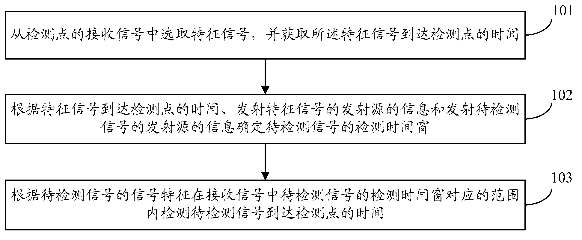
[0087] The embodiment of the present invention provides a flow chart of a signal detection method, see figure 1 , the method flow includes:

[0088] 101: Obtain the time when the characteristic signal arrives at the detection point from the received signal at the detection point.

[0089] Specifically, the time when the characteristic signal arrives at the detection point is obtained from the received signal of the detection point, including:

[0090] Select any undetected signal from the received signal of the detection point as the characteristic signal;

[0091] According to the signal characteristics of any undetected signal, the time when any undetected signal arrives at the detection point is detected within the overall range of the received signal, and the obtained time is used as the time when the characteristic signal arrives at the detection point.

[0092] Specifically, the time when the characteristic signal arrives at the detection point is obtained from the rec...

Embodiment 2

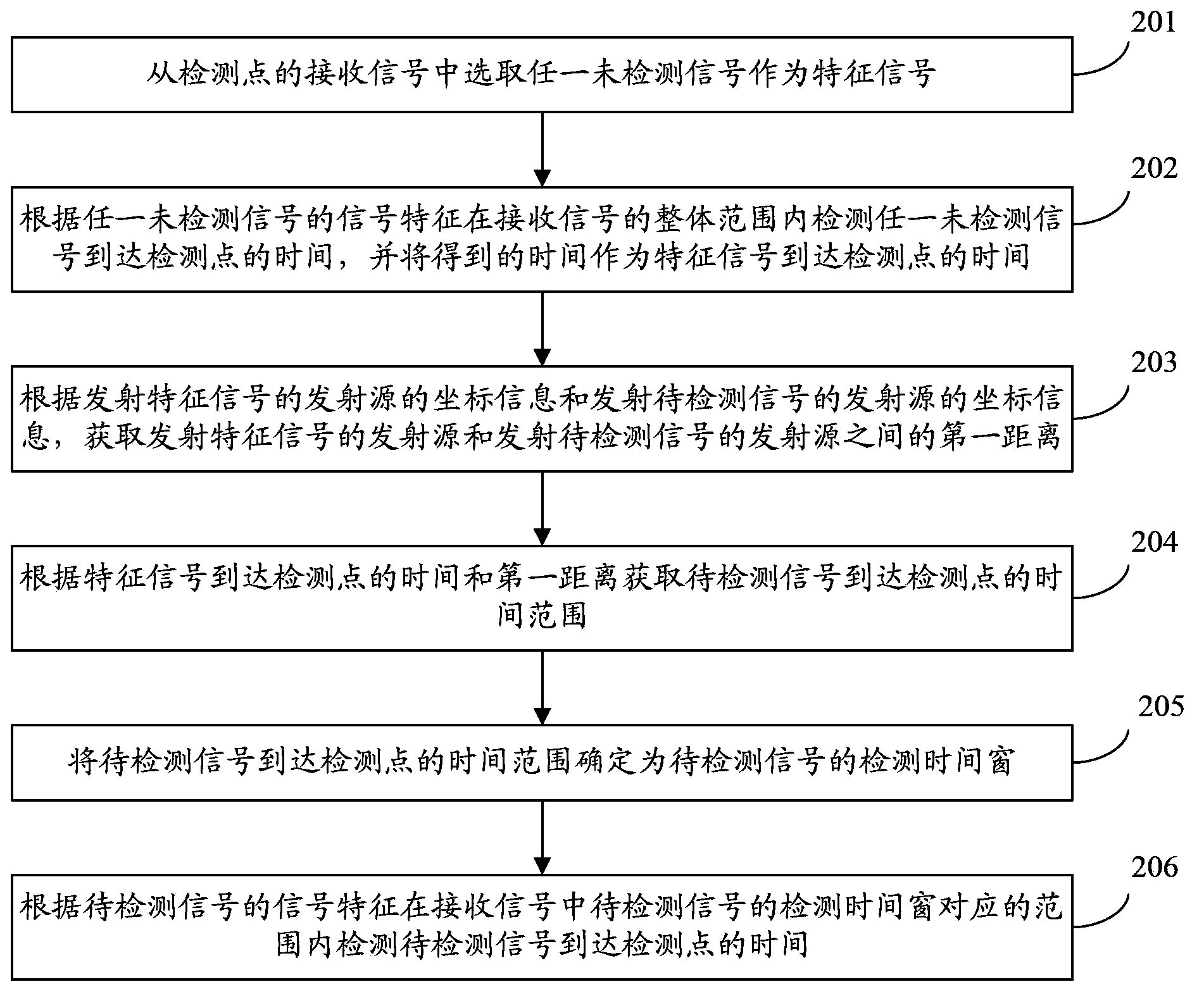
[0119] Combining the content of the first embodiment above, the embodiment of the present invention provides a signal detection method, which is used to detect the signal transmitted by each transmission source in the received signal of the detection point, so as to realize positioning, communication, navigation and other services. The emission source can be satellites, base stations, servers and other equipment, and the detection point can be mobile terminals, tablet computers, sensors, GPS (Global Positioning System, Global Positioning System) navigators and other equipment. see figure 2 , the method flow provided by the embodiment of the present invention includes:

[0120] 201: Select any undetected signal from the received signals at the detection point as the characteristic signal.

[0121] For this step, since the location of the detection point is usually unknown, the distance between the detection point and each transmission source is also unknown, and the time when...

Embodiment 3

[0156] In order to further shorten the time for detecting signals transmitted by multiple transmission sources, the embodiment of the present invention provides another signal detection method on the basis of the first or second embodiment. see Figure 4 , the method flow provided by the embodiment of the present invention includes:

[0157] 401: Select a transmission source whose distance from the transmission source that transmits the signal to be detected is less than a preset distance from the transmission sources that transmit the detected signal, and use the detected signal transmitted by the selected transmission source in the received signal as a characteristic signal.

[0158] Wherein, the number of detected signals can be one or more, and each detected signal is a signal whose arrival time at the detection point is known. 202, it can also be realized through the above steps 203 to 206, in addition, it can also be realized through the methods provided in the embodime...


PUM


Abstract

The invention discloses a signal detection method and device, and belongs to the field of signal processing. The method includes the steps that the time when a characteristic signal arrives at a detection point is obtained from a receiving signal of the detection point; a detection time window of a signal to be detected is determined according to the time when the characteristic signal arrives at the detection point, information of an emission source for emitting the characteristic signal and information of an emission source for emitting the signal to be detected; the time when the signal to be detected arrives at the detection point is detected according to signal characteristics of the signal to be detected in the range corresponding to the detection time window of the signal to be detected in the receiving signal. The detection time window of the signal to be detected is determined according to the time when the characteristic signal arrives at the detection point, the information of the emission source for emitting the characteristic signal and the information of the emission source for emitting the signal to be detected, and the time when the signal to be detected arrives at the detection point is detected in the range corresponding to the detection time window of the signal to be detected in the receiving signal, therefore, the detection time is shortened, and the detection efficiency is improved.

Description

technical field [0001] The invention relates to the field of signal processing, in particular to a signal detection method and device. Background technique [0002] With the promotion of the Internet of Things, positioning, communication, navigation and other technologies are playing an increasingly important role in various fields of national security construction and social development. Aiming at the multi-point distributed system that adopts multi-point distributed mode to realize positioning, communication, navigation and other technologies, it has been widely used because of its high flexibility and strong expansibility. In a multi-point distributed system, multiple transmission sources with fixed positions are usually laid out, and each transmission source transmits a signal to a detection point, where a whole segment of the received signal can be received. In order to realize positioning, communication, navigation and other services, it is necessary to detect the arr...

Claims


Application Information

Patent Timeline
IPC IPC(8): G01S5/02H04W24/00H04W48/20
CPCG01S5/0252G01S5/10
Inventor 黄新华周波杨艳
Owner NEC (CHINA) CO LTD
Learn More