
Portal scaffold

A portal scaffolding and scaffolding technology, which is applied in the field of scaffolding, can solve problems such as personnel injury, increased friction of universal wheels, and scaffolding rolling, so as to prevent personnel injury, enhance stability, and avoid rollover effects

Active Publication Date: 2014-10-01
ANHUI CHANGQING ELECTRONICS MACHINERY GRP
View PDF5 Cites 1 Cited by
  • Summary
  • Abstract
  • Description
  • Claims
  • Application Information

AI Technical Summary

Problems solved by technology

In the prior art, it is generally used to directly block the universal wheel and increase the friction of the universal wheel so that the universal wheel is not easy to roll, but this design is often unsafe. When the buckle fails or the force to push the universal wheel is large enough Sometimes, the scaffolding will still roll, and in the prior art, the construction workers need to extend their upper body out of the range of the platform mechanism to get objects, which increases the risk of people falling from a high place
Moreover, portal scaffolding often adopts a cubic structure, which can easily cause the scaffolding to fall over and cause personal injury.

Method used


Image

  • Portal scaffold

Examples


Embodiment Construction

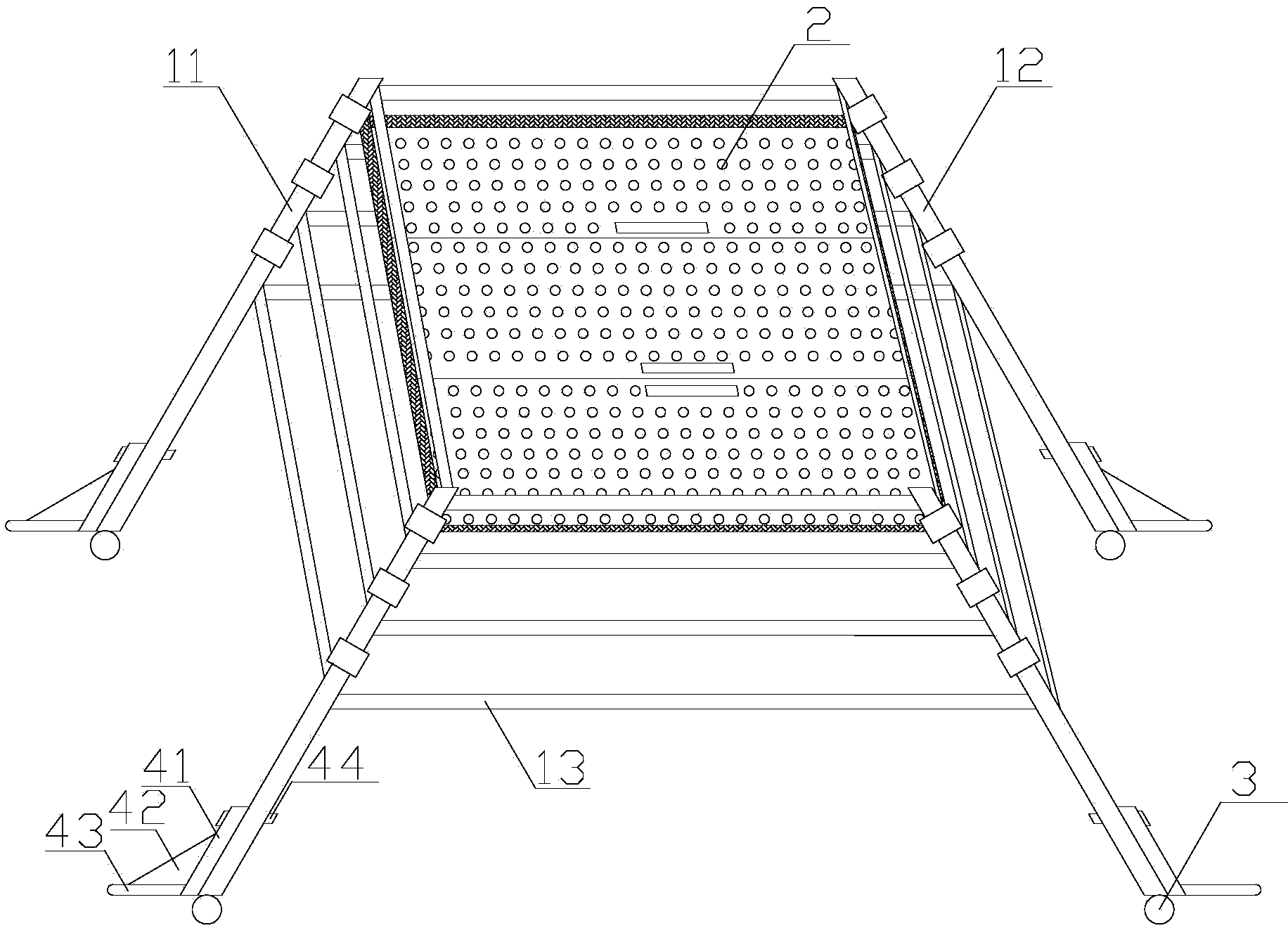
[0013] Such as figure 1 as shown, figure 1 It is a structural schematic diagram of a portal scaffold proposed by the present invention.

[0014] refer to figure 1 , a portal scaffold proposed by the present invention includes a frame, a platform mechanism 2, universal wheels 3 and a fixing mechanism.

[0015] The frame includes a first rod 11, a second rod 12 and a third rod 13, the angle α is formed between the first rod 11, the second rod 12 and the ground, 55°≤α≤75°, and the third rod 13 is parallel Set on the ground, adjacent first rods 11 and second rods 12 are fixedly connected by a third rod 13 to form a door frame A, and two adjacent first rods 11 are fixedly connected by a third rod 13 to form a door frame B. The two second rods 12 are fixedly connected by the third rod 13 to form a door frame C, any two door frames A are parallel to each other, and the door frame B and the door frame C form an angle β, 30°≤β≤55°, the first rod The lower part of 11 is provided wit...


PUM


Abstract

The invention discloses a portal scaffold, which comprises a framework, a platform mechanism, universal wheels and a fixing mechanism, wherein the framework comprises first rods, second rods and third rods; the first rods and the second rods form an included angle alpha with the ground, and alpha is greater than or equal to 55 degrees but smaller than or equal to 75 degrees; the third rods are arranged in a way of being parallel to the ground; the adjacent first rods and second rods are fixedly connected through the third rods for forming portal frames A; the two adjacent first rods are fixedly connected through the third rods for forming portal frames B; the two adjacent second rods are fixedly connected through the third rods for forming portal frames C; any two portal frames A are mutually parallel; the portal frames B and the portal frames C form an included angle beta, and beta is greater than or equal to 0 degrees but smaller than or equal to 55 degrees; in the platform mechanism, a first flat plate, a second flat plate and a third flat plate are respectively hinged to a support frame; and a slide rod in the fixing mechanism upwards or downwards moves to the uppermost part or the bottommost part along the first rods and the second rods so that the universal wheels or a support seat is in contact with the ground. The portal scaffold has the advantages that the structure is simple, and the portal scaffold is of a platform-shaped structure, so the scaffold cannot easily turn over, and the universal wheels cannot easily roll in the use process.

Description

technical field [0001] The invention relates to the technical field of scaffolding, in particular to a portal scaffolding. Background technique [0002] Scaffolding is used in the construction field, and it is convenient for construction personnel to operate and use during decoration and other processes. Universal wheels are installed at the bottom of the portal scaffolding structure, which is convenient for operators to use. In the prior art, it is generally used to directly block the universal wheel and increase the friction of the universal wheel so that the universal wheel is not easy to roll, but this design is often unsafe. When the buckle fails or the force to push the universal wheel is large enough Sometimes, the scaffold still rolls, and in the prior art, the construction personnel need to stretch out the upper body of the platform mechanism to obtain objects, which increases the risk of personnel falling from a height. Moreover, portal scaffolding often adopts a...

Claims


Application Information

Patent Timeline
IPC IPC(8): E04G1/15E04G1/24E04G5/02
Inventor 吴长青何晓俊
Owner ANHUI CHANGQING ELECTRONICS MACHINERY GRP
Learn More