a drying rack

A technology for drying racks and walls, applied in the field of drying racks, can solve the problems of inability to sterilize and sterilize and make full use of the huge space of the balcony, and achieve the effect of saving the space of the balcony and occupying a small space.

Inactive Publication Date: 2016-01-20
GUANGZHOU UNIVERSITY
View PDF5 Cites 0 Cited by
  • Summary
  • Abstract
  • Description
  • Claims
  • Application Information

AI Technical Summary

Problems solved by technology

[0005] 3. Drying clothes can only be carried out in the space of the balcony, and cannot make full use of the huge space outside the balcony;
[0006] 4. Clothes are only dried in the balcony. In many cases, they cannot be directly irradiated by sunlight and cannot achieve the effect of sterilization.

Method used


Image

  • a drying rack
  • a drying rack
  • a drying rack

Examples


Embodiment 1

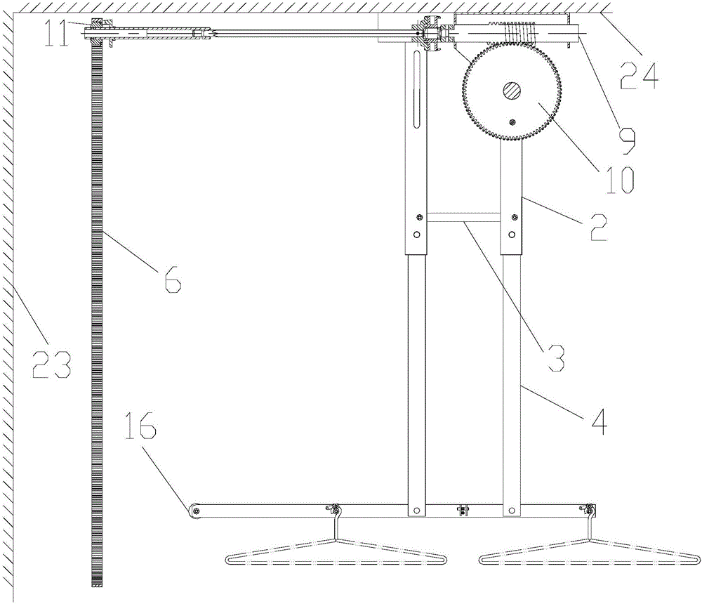
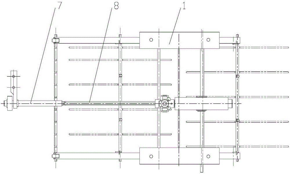
[0031] Such as Figure 1~3 and combine Figure 4 As shown, the whole clothes rack is mainly composed of two trough mounts 1, four swing bars, a clothes frame 5, two connecting rods 3, a drive pin 14, a speed reduction mechanism and a drive mechanism.

[0032] see Figure 1~3 and combine Figure 4 The two channel-shaped mounting bases 1 are made of channel steel and installed perpendicular to the walls of the house and parallel to the ceiling of the balcony, and the flanges of the channel steel are downward.

[0033] see Figure 1~3 and combine Figure 4 , pins are respectively used in the grooves at both ends of each groove-shaped mounting base 1, and among the four swing rods, the upper ends of two are hinged in the grooves at both ends of a groove-shaped mounting base 1 with pins, and the other two The upper end is hinged in the grooves at the two ends of another groove-shaped mounting base 1 with a pin, and the connecting line of the four hinge points connecting the swing...

Embodiment 2

[0044] This embodiment is the same as Embodiment 1 except for the following features.

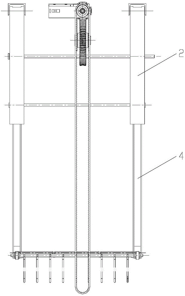
[0045] see Figure 9 , the motor 22 is used to replace the driving mechanism in Embodiment 1, and the output shaft of the motor 22 is connected to the transmission shaft 8 of the worm 9 .


PUM


Abstract

The invention discloses a laundry rack which comprises four oscillating bars (2), an airing frame (5), two connecting rods (3), a driving pin (4) and a driving wheel (10). The upper ends of the four oscillating bars (2) are hinged to the roof of a balcony, the connecting lines of the four hinged joints form a rectangle, and two edges of the rectangle are perpendicular to the wall of a house. Each oscillating bar (2) is formed by connecting an upper oscillating bar body and a lower oscillating bar body in a hinged mode, the side face, far away from the wall of the house, of each upper oscillating bar body is provided with a groove, the upper head of each lower oscillating bar body is hinged to the interior of the groove in the lower head of the corresponding upper oscillating bar body, and the bottom faces of the grooves are used for limiting the oscillating of the lower oscillating rod bodies in the direction of the wall of the house. The laundry rack is capable of airing many clothes, can stretch out of the balcony to be irradiated by sunlight and can be retracted back inside the balcony and lifted, and is convenient to operate, safe and practical.

Description

technical field [0001] The present invention relates to a clothes drying support, in particular to a clothes drying rack attached to a balcony ceiling. Background technique [0002] At present, the known household clothes-drying rack is composed of a clothes-drying pole and a hook on the pole, and the clothes-drying pole is raised and lowered in a certain way to facilitate clothes-drying. This drying rack is convenient to use, but has the following three disadvantages: [0003] 1. If there are many people in the family, and there are many clothes to be dried each time, it cannot be used; [0004] 2. If the balcony is relatively small, the length of the clothes drying pole is limited, and there will be fewer clothes to dry; [0005] 3. Drying clothes can only be carried out in the space of the balcony, and cannot make full use of the huge space outside the balcony; [0006] 4. Clothes are only dried in the balcony. In many cases, they cannot be directly irradiated by sunli...

Claims


Application Information

Patent Timeline
Patent Type & Authority Patents(China)
IPC IPC(8): D06F57/12
CPCD06F57/125
Inventor 游思坤
Owner GUANGZHOU UNIVERSITY
Why Eureka
Try Eureka