Mixing device for reducing agent preparation

A technology of mixing device and additives, applied in mixers, exhaust devices, mixing methods, etc., can solve problems such as increasing exhaust gas back pressure

Active Publication Date: 2017-03-08
VTESCO TECH GMBH
View PDF11 Cites 0 Cited by
  • Summary
  • Abstract
  • Description
  • Claims
  • Application Information

AI Technical Summary

Problems solved by technology

This significantly increases the back pressure of the exhaust gas

Method used


Image

  • Mixing device for reducing agent preparation
  • Mixing device for reducing agent preparation
  • Mixing device for reducing agent preparation

Examples


Embodiment Construction

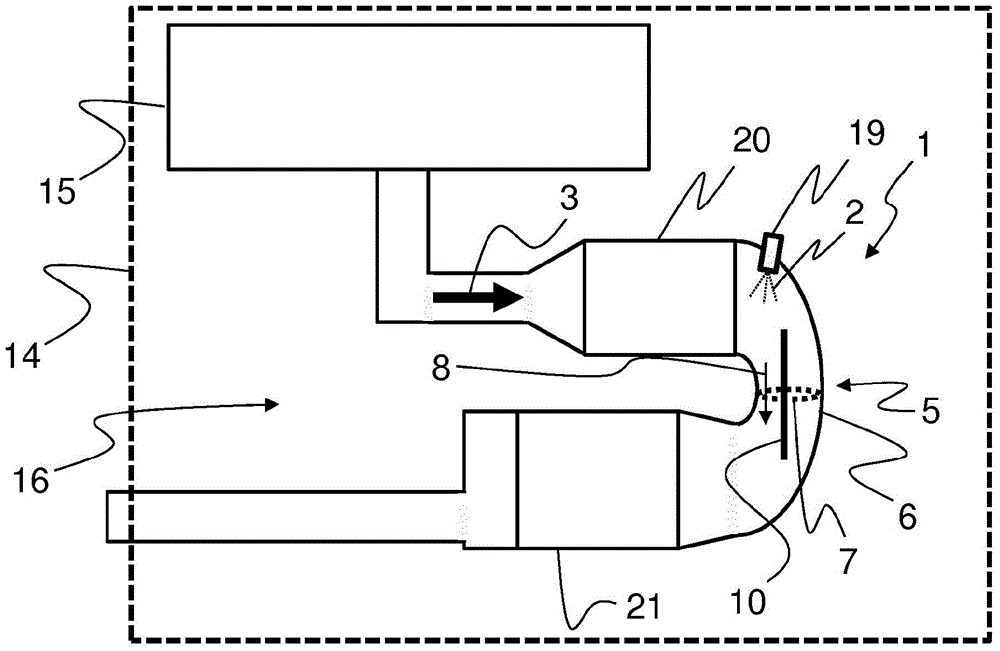
[0031] figure 1 A motor vehicle 14 with an internal combustion engine 15 and an exhaust gas system 16 is shown. The internal combustion engine 15 is preferably a diesel engine or a lean-burn (with excess air) gasoline engine. In this example, the exhaust gas flow 3 in the exhaust system 16 first flows (overflows) through the first exhaust gas purification element 20 and, after flowing through the mixing section 5 , through the second exhaust gas purification element 21 . In this example, an oil injector 19 is connected directly to the connection to the first exhaust gas purification element 20 , which injects the additive 2 into the exhaust gas flow 3 . Arranged in the adjacent mixing device 1 are plates 10 which are oriented in the main flow direction 8 of the exhaust gas flow 3 . This device is a preferred device established in the prior art, but said device does not constitute a restriction of the concept of the invention. The exhaust gas line 6 in the region of the mixi...


PUM


Abstract

Mixing device (1) for mixing an additive (2) with an exhaust gas flow (3), wherein the mixing device comprises at least one overflow plane which is arranged in a mixing section of an exhaust gas line. The exhaust gas duct (6) has a cross section (7) and a main flow direction (8) of the exhaust gas flow (3). The mixing device is characterized in particular in that the at least one overflow plane (4) is arranged centrally in the mixing section (5) and is oriented in the main flow direction (8) of the exhaust gas flow (3), wherein in A plurality of closed recesses (9) are formed in the overflow plane (4). The proposed mixing device achieves efficient mixing of the exhaust gas flow with additives without high flow resistance.

Description

technical field [0001] The invention relates to a mixing device for mixing exhaust gas in an exhaust gas line with an additive, wherein the additive is added, in particular to the exhaust gas, and distributed homogeneously there. In internal combustion engines, especially diesel engines and lean-burn engines, nitrogen oxides occur in undesirably large quantities. In order to remove said nitrogen oxides, it is especially suitable to add the additive ammonia, whereby when there is an excess of oxygen, the nitrogen oxides can be reduced to nitrogen and combined with the hydrogen part of the ammonia to form water. Storage of the irritating gas ammonia has proven unsuitable for mobile use. Conversely, the storage of ammonia in the form of urea dissolved in water has proven suitable for mobile use. For this, use the name A solution containing 32.5% urea has been successful in the market. However, the aqueous urea solution must be prepared accordingly by hydrolysis and / or therma...

Claims


Application Information

Patent Timeline
Patent Type & Authority Patents(China)
IPC IPC(8): B01F3/04B01F5/06F01N3/20
CPCB01F23/213B01F25/4316F01N3/02
Inventor T·内格尔P·阿尔贝蒂
Owner VTESCO TECH GMBH
Why Eureka
Try Eureka