
Construction Laser System

A technology of laser system and building, applied in the field of building laser system

Active Publication Date: 2014-09-24
LEICA GEOSYSTEMS AG
View PDF18 Cites 23 Cited by
  • Summary
  • Abstract
  • Description
  • Claims
  • Application Information

AI Technical Summary

Problems solved by technology

[0029] Furthermore, for the recalibration of rotating lasers, special calibration telescopes are known, such as the one described in, for example, European Patent Application No. EP12195754.2, however, due to the complexities associated therewith, this telescope cannot be used in Often used in practice only for recalibration in the factory

Method used


Image

  • Construction Laser System
  • Construction Laser System
  • Construction Laser System

Examples


Embodiment approach

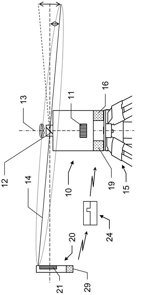
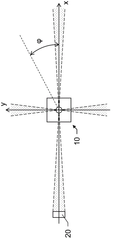
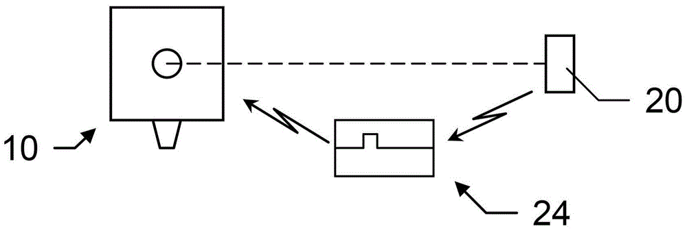
[0130] figure 1 An exemplary embodiment of a construction laser system according to the invention is shown, comprising a rotating laser 10 with a laser unit 11 and a rotatable deflection device 12 for emitting a rotating laser beam 14, wherein the rotating laser a beam-defining reference area; and a laser receiver 20, which includes a laser beam detector 21 extending at least on a one-dimensional area on the laser receiver and designed to respond to the laser beam on the laser beam detector The irradiated position generates an output signal 24 . Furthermore, an evaluation and control unit 16 is provided.

[0131] In this case, the rotating laser 10 has a beam leveling function to be recalibrated, in particular a beam self-leveling function to be recalibrated. To provide this functionality, the rotating laser in this case has

[0132] ●Level sensor,

[0133] a mechanism for at least slightly inclining the axis of rotation with respect to the support of the rotating laser (i...


PUM


Abstract

A construction laser system includes a rotating laser with self-leveling and a laser receiver. The system performs a self-leveling recalibration process by which-the self-leveling is checked automatically for quality and the related calibration data is updated automatically. A sequence of N calibration measurements is defined, where N is greater than or equal to three. The calibration measurements are obtained by the rotating laser and the laser receiver with a respective azimuthal alignment of the stand while the position of the laser receiver remains unchanged. As part of each calibration measurement, one output signal dependent on the laser beam impingement position is detected. The respective output signals or specified impingement positions are evaluated in pairs correlated with the respective I-th azimuthal alignments. The quality of the beam leveling functionality is thereby checked. If the requirements are not met, the previously stored calibration data can then be updated automatically.

Description

technical field [0001] The invention relates to a construction laser system for working in construction and / or interior design, comprising a rotating laser and a laser receiver with improved functionality in terms of configuration complexity and speed of implementation, for determining the distance from the rotating laser Angle to see the direction in which the laser receiver is located. Furthermore, the invention relates to a corresponding method using a rotating laser and a laser receiver, wherein the determination of the direction in which the laser receiver is located from the point of view of the rotating laser is performed in an improved manner, and to a computer program product for implementing the method. Background technique [0002] It is known to use rotating lasers on construction sites (for example of buildings) or in road construction work and / or earthworks. In particular, rotating lasers are used in situations in which a laser beam (in the visible or infrared...

Claims


Application Information

Patent Timeline
IPC IPC(8): G01C15/00
CPCG01C15/008G01C15/004
Inventor T·费斯勒B·施托克尔T·阿默尔
Owner LEICA GEOSYSTEMS AG
Learn More