
Solar illumination device

A lighting device and solar energy technology, which is applied to lighting devices, lighting device parts, lighting device cooling/heating devices, etc., can solve the problem of inability to accurately perceive the opening and closing of light lighting LED lamp groups, and the reduction of natural light collection efficiency , Unfavorable LED light group heat dissipation and other problems, to achieve the effect of eliminating manual maintenance, improving photoelectric conversion efficiency, and avoiding unsafe factors

Active Publication Date: 2014-09-24
SHAANXI PUGUANG ENERGY TECH
View PDF6 Cites 18 Cited by
  • Summary
  • Abstract
  • Description
  • Claims
  • Application Information

AI Technical Summary

Problems solved by technology

[0008] In summary, this type of device has the following problems: first, the lighting device only has a lighting surface in one direction, and the lighting efficiency is low; Effective collection, light concentration, and non-concentrated refraction; third, the hemispherical roof is in the open environment for a long time, and in the absence of manual cleaning, the collection efficiency of natural light caused by floating dust or dirt decreases; fourth, there is no optical sensor , can not accurately perceive light lighting to turn on and off the indoor LED light group; fifth, the LED light group is in the light guide tube, which is not conducive to the heat dissipation of the LED light group and the effective supplementary light effect, and it is easy to communicate with the light guide in the daylighting cover. The inner wall of the light tube condenses into water vapor or dew, which makes maintenance inconvenient

Method used


Image

  • Solar illumination device
  • Solar illumination device
  • Solar illumination device

Examples


Embodiment Construction

[0047] The present invention will be described in detail below in conjunction with the accompanying drawings and specific embodiments, where the schematic embodiments and descriptions of the present invention are used to explain the present invention, but not to limit the present invention.

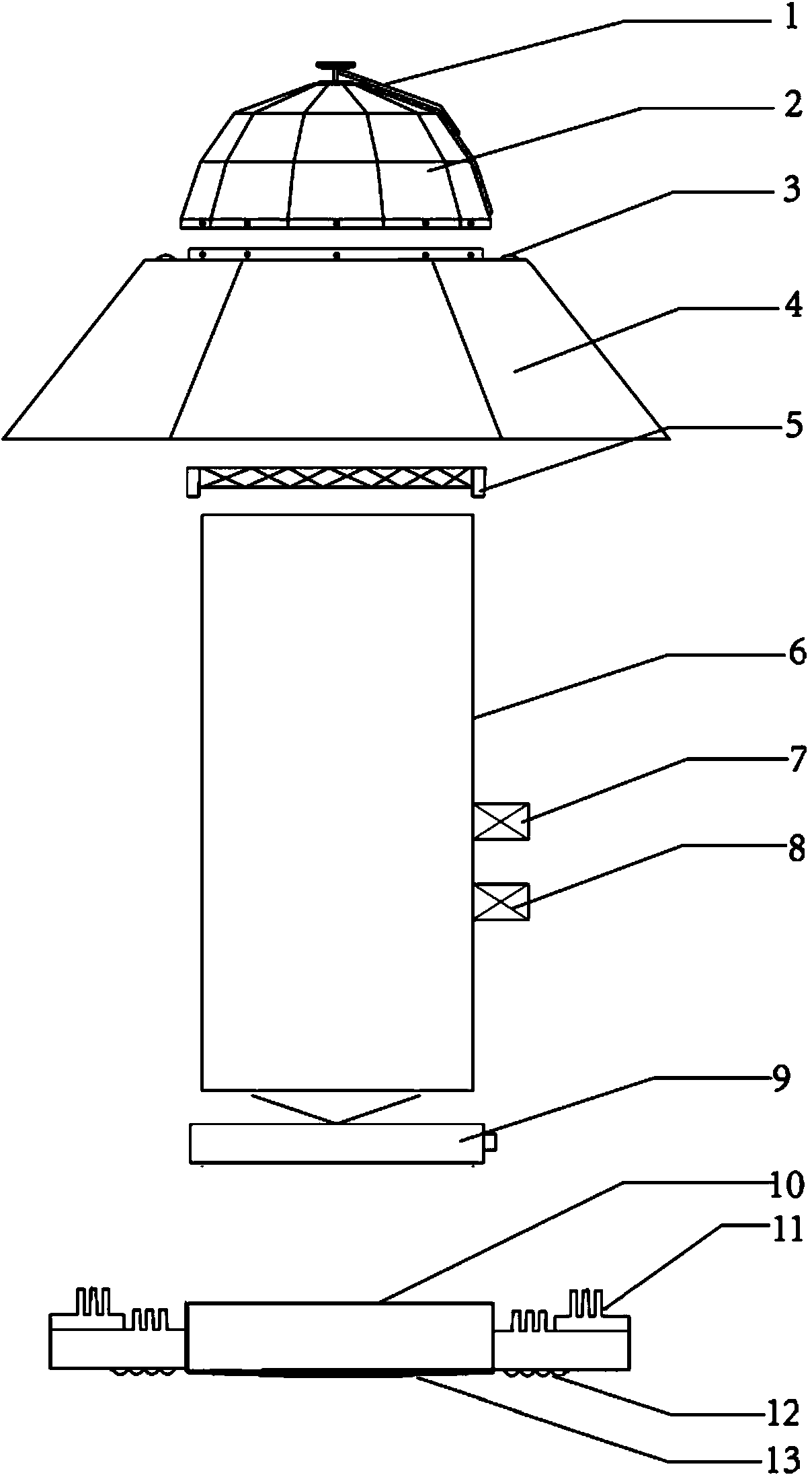
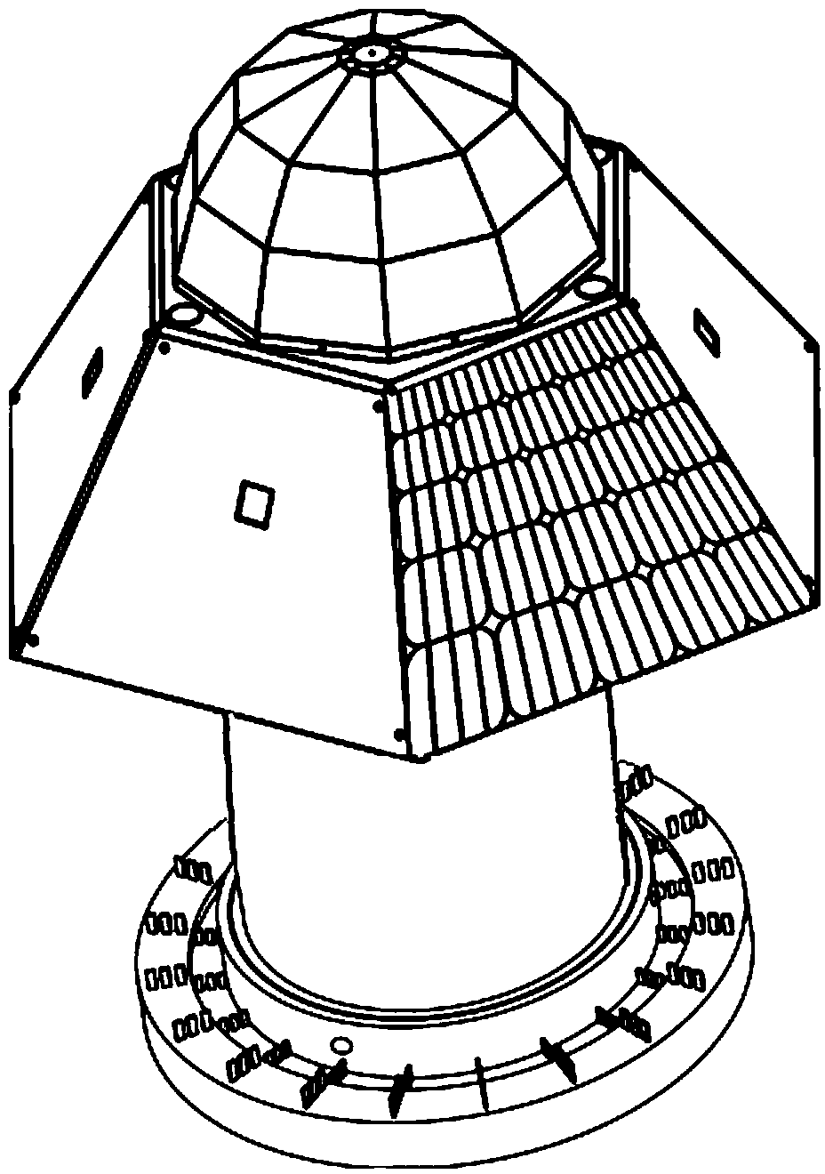
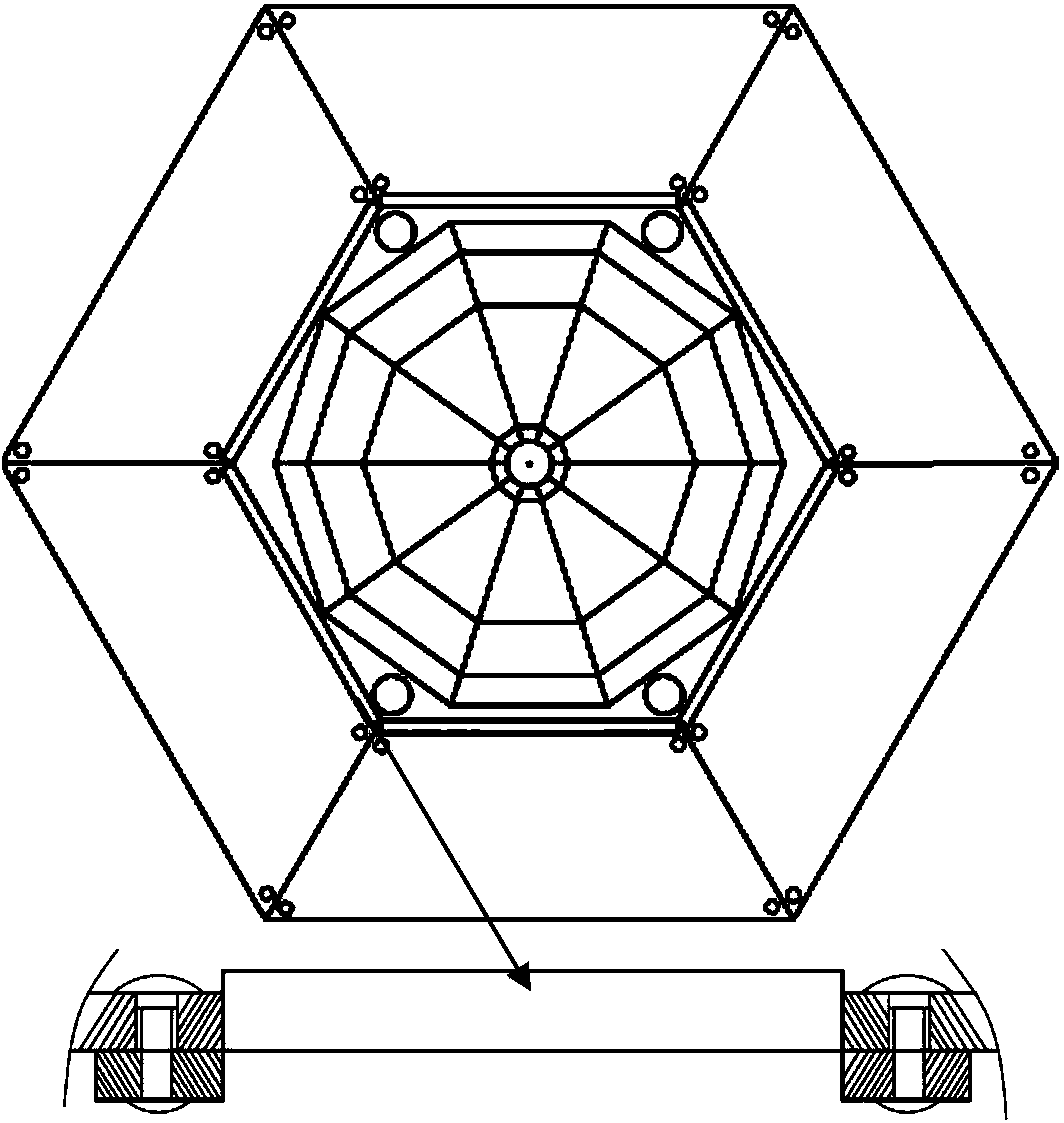
[0048] like figure 1 As shown, a green, low-consumption and environment-friendly solar lighting device described in this specific embodiment includes a natural light collection device 2, and an automatic cleaning device 1 is provided on the top of the natural light collection device 2, so as to avoid the pollution caused by floating dust or dirt. The collection efficiency of natural light decreases. The natural light collecting device 2 is buckled and sealed to connect with the solar panel base complex 4, and fixed with anti-theft screws. There are four solar photometric sensors 3 on the solar panel base complex 4, which are used to sense and collect outdoor natural light intensity. When...


PUM


Abstract

The invention discloses a solar illumination device which comprises a natural light collecting device. The top of the natural light collecting device is provided with an automatic cleaning device, a solar battery plate base recombiner is connected with the lower portion of the natural light collecting device in a buckled and sealed mode and is provided with multiple solar luminosity sensors, a reflection grating assembly is arranged on the inner wall of the solar battery plate base recombiner in a buckled mode, the lower end of the reflection grating assembly is fixedly provided with a light guide tube, a dimming device is arranged in the light guide tube, the dimming device is provided with a storage battery and a solar intelligent controller on the outer wall of the light guide tube, the storage battery is connected with a photovoltaic power generation assembly and the solar intelligent controller in the solar battery plate base recombiner through wires, the bottom end of the light guide tube is connected with a solar illumination device base, the bottom of the base is connected with a diffuser, and the base is provided with an LED illumination lamp set provided with an LED radiator in a matched mode. A natural light source is used for lighting and illumination during the day, photovoltaic power is combined with the LED lamp set for illumination at night, and accordingly the illumination requirements of use areas in a building are met.

Description

technical field [0001] The invention relates to a device for architectural lighting, in particular to a green, low-consumption and environment-friendly solar lighting device. Background technique [0002] At present, indoor lighting is generally provided with windows in the building, and external sunlight is introduced into the room through the windows. For buildings that are relatively closed and cannot be directly illuminated, lighting fixtures are generally used for indoor lighting. During the use of lighting lamps, it not only wastes electric energy, but also has potential safety hazards, especially for some processing workshops, shopping malls, underground garages and other environments. In addition, electric lighting can only provide lighting with a single wavelength, while the emission spectrum of sunlight has a wider band, and lighting with sunlight makes people feel more comfortable. [0003] In order to introduce sunlight into buildings that cannot be directly ill...

Claims


Application Information

Patent Timeline
IPC IPC(8): F21S19/00F21V23/00F21V13/12F21V23/04F21V29/00H05B37/02F21Y101/02F21Y115/10
CPCY02B20/40
Inventor 刘洋
Owner SHAANXI PUGUANG ENERGY TECH
Learn More