
End face drilling tool

A drilling tool and hydraulic cylinder technology, applied in the field of mechanical processing, can solve the problems of high processing cost, inability to guarantee accuracy, and high equipment cost, and achieve the effects of reliable processing quality, elimination of adverse effects, and simple and flexible operation.

Inactive Publication Date: 2014-09-24
ZUNYI CHANGJIA MACHINERY MFG CO LTD
View PDF8 Cites 6 Cited by
  • Summary
  • Abstract
  • Description
  • Claims
  • Application Information

AI Technical Summary

Problems solved by technology

[0003] There are three conventional processing methods: the first is to use a machining center. The advantage of this method is that the dimensional accuracy and shape and position tolerance can meet the requirements of the design drawings; the disadvantage is that the equipment cost is high, and it is not suitable for a large number of developments by outsourced manufacturers. resulting in high processing costs
The second is to use a milling machine for processing. Although the processing quality of the product can be guaranteed, the production efficiency is low and it cannot meet the delivery cycle requirements of the product.
The third is to use the fitter's general drilling mold processing. The advantage is that the operation is flexible, and the disadvantage is that the accuracy requirements cannot be guaranteed.

Method used


Image

  • End face drilling tool
  • End face drilling tool
  • End face drilling tool

Examples


Embodiment Construction

[0017] The technical solution of the present invention is further described below in conjunction with the accompanying drawings, but the scope of protection is not limited to the description.

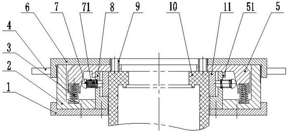
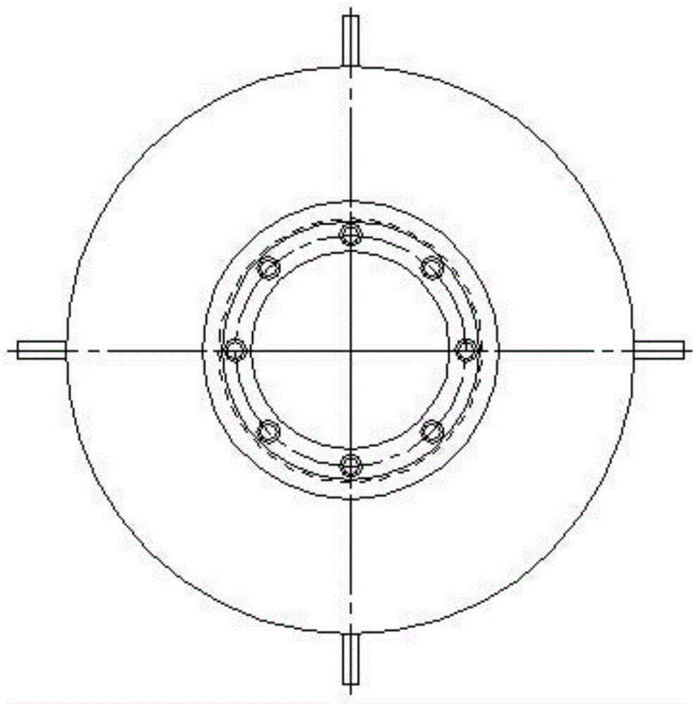
[0018] like figure 1 , figure 2 , image 3 As shown, a hydraulic cylinder liner end face drilling tooling according to the present invention includes a lower cover plate 1 and an upper cover plate 6 with openings installed oppositely, and a screw is arranged between the upper cover plate 6 and the lower cover plate 1. Cover 2, inner positioning sleeve 8 and mold sleeve 5, the open end of the screw sleeve 2 is threadedly connected with the upper cover plate 6, and the bottom surface is processed with a center hole; the lower end of the inner positioning sleeve 8 is nested in the bottom center of the screw sleeve 2 In the hole; the bottom of the inner positioning sleeve 8 and the screw sleeve 2 are respectively connected with the lower cover plate 1, and both the inner positioning slee...


PUM


Abstract

The invention discloses an end face drilling tool for a hydraulic cylinder sleeve, and belongs to the technical field of machining. The drilling tool comprises a lower cover plate and an upper cover plate, which are arranged in a way that openings of the upper and lower cover plates are opposite to each other, wherein a threaded sleeve, an inner positioning sleeve and a die sleeve are arranged between the upper and lower cover plates; the open end of the threaded sleeve is in threaded connection with the upper cover plate, and a center hole is machined in the bottom surface of the threaded sleeve; the lower end of the inner positioning sleeve is nested in the center hole in the bottom of the threaded sleeve; the inner positioning sleeve and the bottom of the threaded sleeve are connected with the lower cover plate respectively; each of the inner positioning sleeve and the lower cover plate is provided with a center hole; the inner wall of the die sleeve has a conical surface structure, and is arranged between the upper cover plate and the inner positioning sleeve in an upturning way; one-to-one corresponding spring mounting grooves are machined in the end face of the die sleeve and the bottom surface of the threaded sleeve respectively; resetting springs are arranged in the mounting grooves. According to the technical scheme, the die sleeve is matched with a ball pushrod structure for elastic alignment, so that adverse effects of overall dimension fluctuation on a drilling position can be eliminated, and an effect of rapid and accurate alignment is achieved.

Description

technical field [0001] The invention belongs to the technical field of mechanical processing, and relates to a drilling tool, in particular to a drilling tool for the end face of a hydraulic cylinder sleeve. Background technique [0002] When processing a certain type of hydraulic cylinder liner, it is necessary to process 8-12 threaded holes on the end surface for connecting other parts and installing gaskets, and the hole position requirement is 0.2. [0003] There are three conventional processing methods: the first is to use a machining center to process. The advantage of this method is that the dimensional accuracy and shape and position tolerance can meet the requirements of the design drawings; the disadvantage is that the equipment cost is high, and it is not suitable for a large number of development by outsourcing manufacturers. As a result, the processing cost of the product is high. The second is to use a milling machine for processing. Although the processing q...

Claims


Application Information

Patent Timeline
Patent Type & Authority Applications(China)
IPC IPC(8): B23Q3/00B23B47/28
CPCB23B47/28B23B2247/12
Inventor 刘梅
Owner ZUNYI CHANGJIA MACHINERY MFG CO LTD
Learn More