
Display method, system and optical time domain reflectometer for optical fiber detection

An optical fiber detection and display method technology, applied in transmission systems, electromagnetic wave transmission systems, electrical components, etc., can solve the problem of low event accuracy, and achieve the effect of accurate and display, simplified data volume, and rapid display

Inactive Publication Date: 2016-12-07
INNO INSTR (CHINA) INC
View PDF0 Cites 0 Cited by
  • Summary
  • Abstract
  • Description
  • Claims
  • Application Information

AI Technical Summary

Problems solved by technology

[0009] In view of the shortcomings of the prior art described above, the object of the present invention is to provide a display method, system and optical time domain reflectometer for optical fiber detection, which are used to solve the problem of inaccuracy of events displayed during optical fiber detection in the prior art. high problem

Method used


Image

  • Display method, system and optical time domain reflectometer for optical fiber detection
  • Display method, system and optical time domain reflectometer for optical fiber detection
  • Display method, system and optical time domain reflectometer for optical fiber detection

Examples


Embodiment Construction

[0026]Embodiments of the present invention are described below through specific examples, and those skilled in the art can easily understand other advantages and effects of the present invention from the content disclosed in this specification. The present invention can also be implemented or applied through other different specific implementation modes, and various modifications or changes can be made to the details in this specification based on different viewpoints and applications without departing from the spirit of the present invention. It should be noted that, in the case of no conflict, the following embodiments and features in the embodiments can be combined with each other.

[0027] It should be noted that the diagrams provided in the following embodiments are only schematically illustrating the basic ideas of the present invention, and only the components related to the present invention are shown in the diagrams rather than the number, shape and shape of the compon...


PUM


Abstract

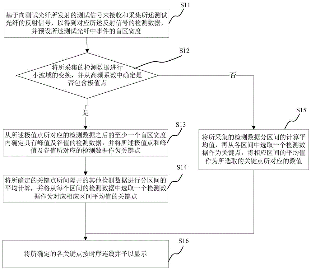
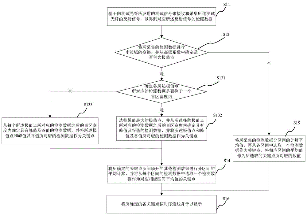
The invention provides a display method and system for optical fiber detection and an optical time domain reflectometer. According to the method, the system receives and collects the reflection signal of the test fiber based on the test signal transmitted to the test fiber to obtain the detection data corresponding to the reflection signal, and presets the width of the dead zone of the event in the test fiber; the collected Transform the detection data in the wavelet domain, and determine the extreme points from the high-frequency coefficients; determine the detection data with peaks and valleys from the blind zone width after the detection data corresponding to the extreme points, and convert the extreme points The detection data corresponding to the peak value and the valley value are taken as the key points; the other detection data separated by the determined key points are calculated as the average of the intervals, and one detection data is selected from the detection data of each interval as the corresponding The key point of the average value of the corresponding interval; the determined key points are connected in time series and displayed. In this way, the detected waveform can be displayed accurately and quickly.

Description

technical field [0001] The invention relates to a display method for optical fiber detection, in particular to a display method, system and optical time domain reflectometer for optical fiber detection. Background technique [0002] The optical time domain reflectometer is an instrument for understanding the uniformity, defect, fracture, joint coupling and other properties of the optical fiber through the analysis of the measurement curve. It is made according to the principle of light backscattering and Fresnel reflection, and uses the backscattering light generated when light propagates in the fiber to obtain attenuation information, which can be used to measure fiber attenuation, joint loss, fiber fault location and understand fiber Loss distribution along the length, etc., is an indispensable tool in the construction, maintenance and inspection of optical cables. The optical time domain reflectometer provides technicians with the detection status of the optical fiber by...

Claims


Application Information

Patent Timeline
Patent Type & Authority Patents(China)
IPC IPC(8): H04B10/071
Inventor 单俊涛
Owner INNO INSTR (CHINA) INC
Learn More