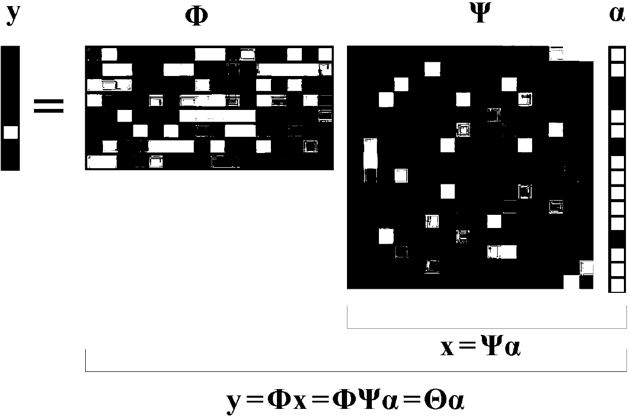
Signal reconstruction method for frequency domain sparse signals
A sparse signal and signal reconstruction technology, applied in the field of signal processing, can solve the problems of large data storage space, long time consumption, large amount of calculation and so on
- Summary
- Abstract
- Description
- Claims
- Application Information
AI Technical Summary
Problems solved by technology
Method used
Image
Examples
specific Embodiment approach 1
[0079]Specific implementation mode 1: step 1 described in this implementation mode, use the analog-to-digital converter to collect the output signal of the filter, and obtain a series of sampling values, which are recorded as y(m), (m=1, 2,..., M), according to the generation mode of the MLS sequence itself and the output sampling rate fs, calculate a series of values of the MLS sequence input to the multiplier within the sampling time t, denoted as p(n), (n=1,2,.. .,N),
[0080] Step 2: Input a 1V DC signal to one input terminal of the multiplier, and input a rectangular pulse signal to the other input terminal. The low level of the signal is 0V, the high level is 1V, and the high level duration is 0.1ms; and At the same time, use an analog-to-digital converter to collect the output signal of the low-pass filter, the sampling rate and sampling time are the same as fs and t in step 1, and the collected result is the impulse response of the multiplier and the low-pass filter,...
specific Embodiment approach 2
[0126] Specific embodiment two: the difference between this embodiment and specific embodiment one is: the acquisition process of y(m) in step one is:
[0127] The signal to be tested is input to one input terminal of the multiplier, and the other input terminal of the multiplier is used to input the MLS sequence; the output terminal of the multiplier is connected to the input terminal of the low-pass filter, and the output terminal of the low-pass filter is connected to the analog-to-digital conversion The input terminal of the converter is connected, and the output terminal of the analog-to-digital converter is connected with the input terminal of the host computer;
[0128] Input a measured analog signal x(t) and a MLS sequence p(t) into a multiplier for multiplication, the multiplied signal is filtered by a low-pass filter, and the filtered signal is sampled by an analog-to-digital converter. The sampling rate used during sampling is fc, the sampling time is t, and a serie...
specific Embodiment approach 3
[0129] Specific embodiment three: the difference between this embodiment and specific embodiment one or two is: the acquisition process of p(n) in step one is:
[0130] The MLS sequence is a series of values calculated according to the set mode, and then output these values one by one at the set sampling rate fs with the help of an arbitrary waveform generator to form an MLS sequence, because its generation mode and output sampling rate have been set Known, so all the values of the MLS sequence within the sampling time t can be calculated, denoted as p(n), (n=1,2,...,N), N=fs×t;
[0131] The output sampling rate fs of the MLS sequence and the sampling rate fc used by the sampling filter output signal have the following relationship: fs=C×fc, and naturally have the following relationship N=C×M, C is an integer. combine Figure 3 to Figure 6 This embodiment mode is explained. Other steps and parameters are the same as those in Embodiment 1 or Embodiment 2.
PUM
 Abstract
Description
Claims
Application Information
 - R&D
- Intellectual Property
- Life Sciences
- Materials
- Tech Scout
- Unparalleled Data Quality
- Higher Quality Content
- 60% Fewer Hallucinations
Browse by: Latest US Patents, China's latest patents, Technical Efficacy Thesaurus, Application Domain, Technology Topic, Popular Technical Reports.
© 2025 PatSnap. All rights reserved.Legal|Privacy policy|Modern Slavery Act Transparency Statement|Sitemap|About US| Contact US: help@patsnap.com


