
Preparation method of semiconductor device

A technology for semiconductors and devices, applied in the field of semiconductor device preparation, can solve the problems that cannot be realized and easily cause shading effects (SHADOW-EFFECT, device performance degradation, etc.)

Active Publication Date: 2014-09-17
SEMICON MFG INT (SHANGHAI) CORP
View PDF5 Cites 2 Cited by
  • Summary
  • Abstract
  • Description
  • Claims
  • Application Information

AI Technical Summary

Problems solved by technology

[0005] Compared with the gate first process (gate first), in the "gate last (high-K&gate last)" process, not only the metal is filled in the trench, but also the high-K dielectric and covering layer (cap layer), so the filling of the void after etching and removing the dummy gate in the gate-last (high-K&gate last) process becomes a key issue. In the prior art, in order to improve the filling of the void in the gate-last (high-K&gate last) process, The method of increasing the critical dimension of the dummy gate is usually adopted. When the critical dimension of the dummy gate is too large, it is easy to cause the shadowing effect (SHADOW-EFFECT) during the lightly doped drain (LDD) ion implantation process, resulting in Device performance degradation
[0006] Therefore, as the size of semiconductor devices continues to decrease, especially when the device size drops below 20nm, how to expand the critical size of the metal gate and at the same time make the device have better performance is an urgent issue in the current metal gate preparation process. The technical problems to be solved, none of the current technical means can achieve the stated purpose

Method used


Image

  • Preparation method of semiconductor device
  • Preparation method of semiconductor device
  • Preparation method of semiconductor device

Examples


Embodiment Construction

[0047] In the following description, numerous specific details are given in order to provide a more thorough understanding of the present invention. It will be apparent, however, to one skilled in the art that the present invention may be practiced without one or more of these details. In other examples, some technical features known in the art are not described in order to avoid confusion with the present invention.

[0048] For a thorough understanding of the present invention, a detailed description will be presented in the following description to explain the method of manufacturing the semiconductor device of the present invention. Obviously, the practice of the invention is not limited to specific details familiar to those skilled in the semiconductor arts. Preferred embodiments of the present invention are described in detail below, however, the present invention may have other embodiments besides these detailed descriptions.

[0049] It should be noted that the terms...


PUM


Abstract

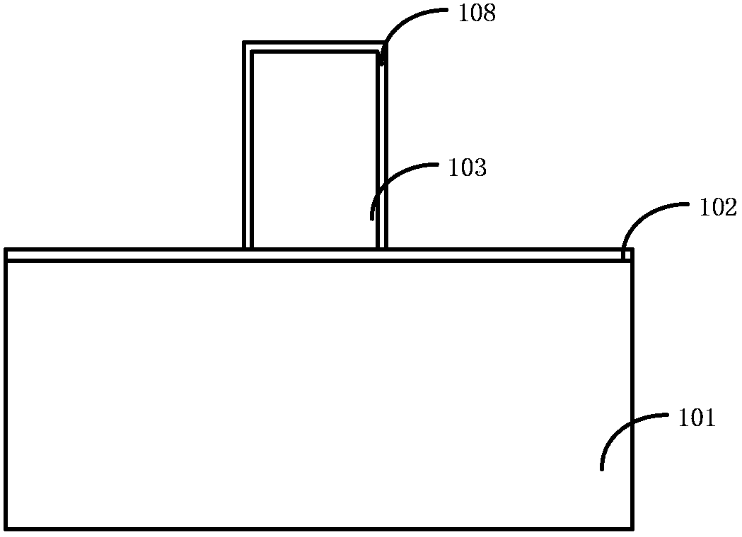
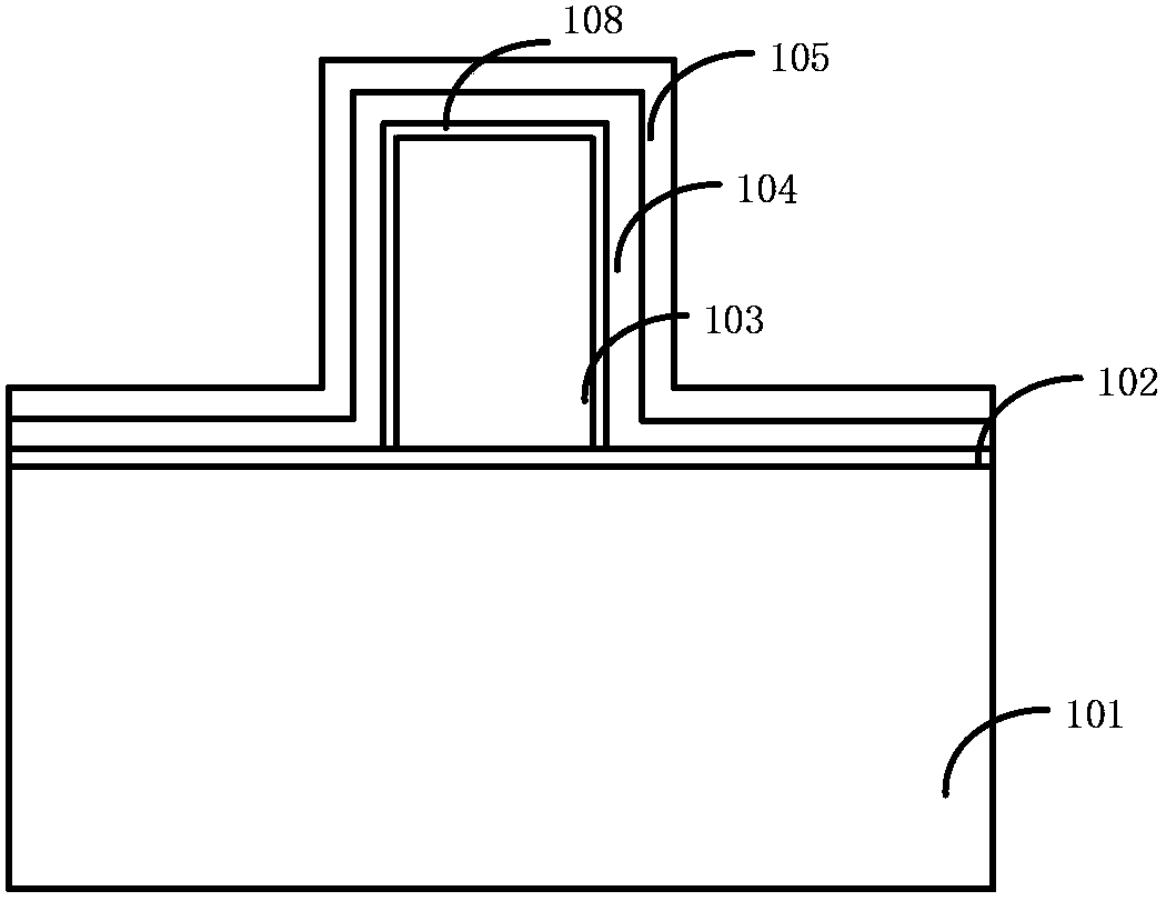
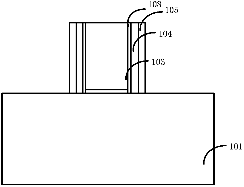
The invention relates to a preparation method of a semiconductor device. The method comprises: providing a semiconductor substrate; forming a virtual gate on the semiconductor substrate; forming a first offset side wall and a second offset side wall at the side of the virtual gate; removing the virtual gate; and removing the first offset side wall to form a groove with the increased critical dimension. According to the invention, after the virtual gate is formed, a thermal treatment oxide layer, the first offset side wall, and the second offset side wall are formed on the virtual gate; and after LDD and source-drain ion injection are executed, the thermal treatment oxide layer and the first offset side wall are removed to form the groove, wherein the critical dimension of the groove is the critical dimension of the metal gate and the critical dimension of the metal gate is larger than that of the conventional metal gate. Moreover, the thermal treatment oxide layer and the first offset side wall are formed after the source-drain ion injection, so that the large critical dimension is obtained and the shadow effect can be avoided and thus the device performance is improved.

Description

technical field [0001] The invention relates to a semiconductor device technology, in particular, the invention relates to a method for preparing a semiconductor device. Background technique [0002] With the continuous development of semiconductor technology, the improvement of integrated circuit performance is mainly achieved by continuously shrinking the size of integrated circuit devices to increase its speed. At present, since the semiconductor industry has advanced to the nanotechnology process node in the pursuit of high device density, high performance and low cost, especially when the size of semiconductor devices is reduced to 20nm or below, the fabrication of semiconductor devices is limited by various physical limits. [0003] When the size of a semiconductor device is reduced to 20nm or below, the gate critical dimension (gate CD) in the device is correspondingly reduced to 24nm. With the reduction of technology nodes, the traditional gate dielectric layer cont...

Claims


Application Information

Patent Timeline
IPC IPC(8): H01L21/28H01L21/336
CPCH01L21/28008H01L29/401H01L29/4232H01L29/66545
Inventor 赵杰
Owner SEMICON MFG INT (SHANGHAI) CORP
Learn More