
A Tiller Engine and Handle Seat Mounting Structure

A technology of installation structure and handle seat, which is applied in the field of micro tillage machines, can solve the problems of inconvenient selection of suitable power for micro tillage machines, poor reliability of handle seat connections, and large space occupied by vertical engines, so as to achieve the convenience of crossing obstacles , good reliability and compact structure

Active Publication Date: 2016-07-06
CHONGQING JIAMU MACHINERY
View PDF5 Cites 0 Cited by
  • Summary
  • Abstract
  • Description
  • Claims
  • Application Information

AI Technical Summary

Problems solved by technology

The existing micro-tiller frame not only has complex structure, difficult processing and high production cost, but also takes up a lot of space, which will increase the volume of the entire micro-tiller, which is not conducive to the development of micro-tillers in the direction of miniaturization
[0004] The powertrain on the tiller usually uses a vertical engine. On the one hand, there are few types of vertical engines, which is not convenient for the tiller to choose the appropriate power according to actual needs; on the other hand, the vertical engine is on the frame. It takes up a lot of space and will increase the volume of the whole tiller
[0005] The handle on the tiller is generally composed of a handle tube and a handle seat, and the handle tube and the handle seat are usually in one structure, so that the space is large and will increase the cost of packaging and transportation; at the same time, the handle seat is connected on the frame The reliability is poor, and the disassembly operation is inconvenient

Method used


Image

  • A Tiller Engine and Handle Seat Mounting Structure
  • A Tiller Engine and Handle Seat Mounting Structure
  • A Tiller Engine and Handle Seat Mounting Structure

Examples


Embodiment Construction

[0024] The present invention will be further described below in conjunction with the drawings and embodiments:

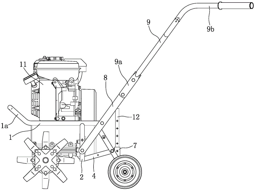
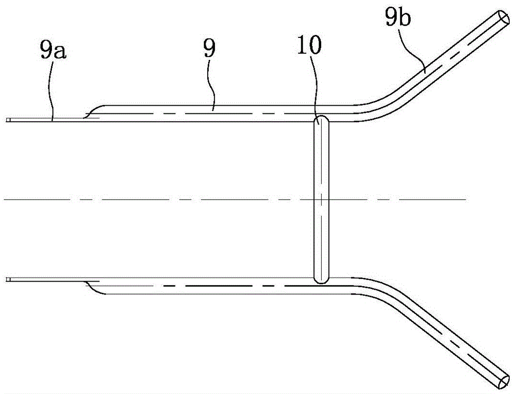
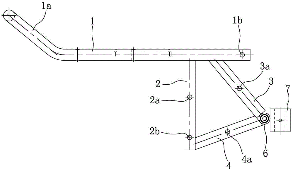
[0025] Such as figure 1 , figure 2 , image 3 , Figure 4 with Figure 5 As shown, the frame is composed of a main pipe 1, a vertical pipe 2, a first inclined pipe 3, a second inclined pipe 4, a supporting plate 5, a horizontal pipe 6 and a positioning sleeve 7. Among them, the main pipe 1 is a "U" shape with the front end closed and the rear end opening. The front end of the main pipe 1 is tilted upward to form a bumper 1a. The bumper 1a and the horizontal section of the main pipe 1 have an angle of 130-150° . A pallet 5 is provided in the middle between the two horizontal sections of the main pipe 1. The pallet 5 has a rectangular flat structure. The end of the pallet 5 overlaps with the pipe body of the corresponding horizontal section of the main pipe 1, and is fixed by welding . Four strip holes 5a are distributed on the pallet 5 in a rectangular shape, and th...


PUM


Abstract

The invention discloses a mini-tiller engine and handle bracket installing structure comprising a rack, an engine (11) and handle brackets (8) in a bilateral symmetry mode. The rack is provided with a main pipe (1), the main pipe (1) is in a U shape with the closed front end and the open rear end, the front end of the main pipe (1) upwarps to form a bumper (1a), a supporting board (5) is arranged in the middle of the space between two horizontal sections of the main pipe (1), the engine (11) is supported on the supporting board (5), an output shaft of the engine (11) extends out horizontally and backwards, and the bottom of the engine (11) is fixedly connected with the supporting board (5) through four bolts distributed in a rectangular mode. The engine is a horizontal engine and is large in choice space, and the size of a mini-tiller can be further decreased; the engine is firmly installed and is reliable and good in smoothness. The handle brackets and handle tubes of a handle are of a split structure and can be assembled or disassembled conveniently and fast, and cost of package and transportation can be effectively lowered.

Description

Technical field [0001] The invention belongs to the technical field of micro-tillers, and specifically relates to an engine and a handle seat mounting structure on the micro-tiller. Background technique [0002] The micro-tiller is an agricultural appliance in the new era. It has the characteristics of light weight, small size and simple structure. It is widely used in dry land, paddy fields, orchards in plains, mountainous areas and hills. It can be equipped with corresponding equipment for pumping, power generation, and spraying. , Spraying and other operations, and towing trailers for short-distance transportation. The micro-tiller has strong flexibility, can travel freely in the field, is convenient for users to use and store, saves the trouble that large agricultural machinery cannot enter the mountain fields, and saves a lot of time for farmers in the busy season. [0003] The frame is an important part of the micro-tiller and the skeleton of the micro-tiller, which is used ...

Claims


Application Information

Patent Timeline
Patent Type & Authority Patents(China)
IPC IPC(8): B62D51/04
Inventor 邵海波向安林
Owner CHONGQING JIAMU MACHINERY
Learn More