
Adjustable hinge

An adjustable, hinged technology, applied in folding boards, door/window accessories, construction, etc., can solve the problems of low production efficiency of printing process, inconsistent upper and lower gaps, expansion openings of shaft sleeves, etc. The gap is uniform and the effect of avoiding deformation opening

Active Publication Date: 2014-09-10
浙江科秀五金有限公司
View PDF7 Cites 4 Cited by
  • Summary
  • Abstract
  • Description
  • Claims
  • Application Information

AI Technical Summary

Problems solved by technology

[0003] One purpose of the present invention is to solve the problem of inconsistent upper and lower gaps in existing hinges after installation of doors and windows, and to provide an adjustable hinge that can adjust the upper and lower gaps after installation of doors and windows to ensure that the doors and windows no sticking
[0004] Another object of the present invention is to solve the problem of low bushing strength in the existing hinges, which is prone to expansion and opening due to force, and to provide a hinge with high bushing strength, which can effectively avoid the hinge The expansion and opening of the sleeve occurs during use
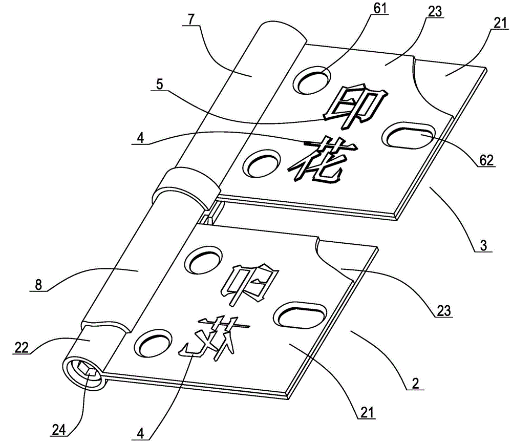
[0005] The third purpose of the present invention is to solve the problem of low production efficiency of the printing process existing in the existing hinges, and provide a hinge with convenient processing, high production efficiency and good printing quality.

Method used


Image

  • Adjustable hinge
  • Adjustable hinge
  • Adjustable hinge

Examples


Embodiment Construction

[0038] The present invention will be further described below in conjunction with the accompanying drawings and specific embodiments.

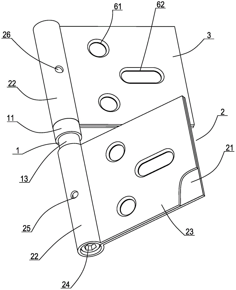
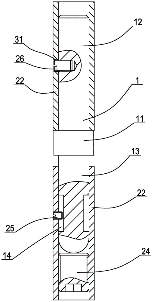
[0039] Such as figure 1 As shown, an adjustable hinge includes a left leaf 2, a right leaf 3 and a shaft rod 1, and the left and right leafs include a substrate 21 provided with a fixing hole for installation, and one side of the substrate faces outward. The sleeve 22 formed by curling is extended and bent toward the upper surface side of the substrate. Such as figure 2 As shown, the middle part of the shaft is provided with an outwardly protruding collar 11, thereby separating the shaft into an upper section 12 and a lower section 13. The bushing of the right leaf is rotatably connected to the upper section on the upper side of the collar on the shaft, while the left leaf The shaft sleeve of the sheet is then rotatably connected to the lower section of the lower side of the collar on the shaft, and the shaft sleeve of the left sheet is prov...


PUM


Abstract

The invention discloses an adjustable hinge. The adjustable hinge comprises a left hinge, a right hinge and a shaft lever; each of the left hinge and the right hinge comprises a base plate and a shaft sleeve, wherein each base plate is provided with a fixing hole for mounting; each shaft sleeve is formed by outwards extending one side edge of the base plate and bending and curving toward one side of the upper surface of the base plate; an outwards convex shaft ring is arranged in the middle part of the shaft lever, which divides the shaft lever into an upper section and a lower section; the shaft sleeves of the right hinge and the left hinge are respectively rotatably connected with the upper section and the lower section at two sides of an upper shaft ring of the shaft lever; an adjusting bolt is in threaded connection with the inner lower end of the shaft sleeve of the left hinge, far from the shaft ring; the inner end surface of the adjusting bolt is connected against the end surface of the lower section of the shaft lever; reinforcing sheets which are clung to the upper surfaces of the base plates outwards extend from the side edges of openings in the shaft sleeves of the left hinge and the right hinge; the reinforcing sheets pass through the fixing holes for mounting in the base plates. With the adoption of the adjustable hinge, the upper and lower gaps between a door and a door frame can be adjusted, the shaft sleeves are high in intensity, and thus the phenomenon that the shaft sleeves are expanded and opened when using the hinge can be avoided; the processing is convenient; the production efficiency is high; in addition, printed patterns are high in quality.

Description

technical field [0001] The invention relates to a connecting member for installing doors and windows, in particular to a hinge with high structural strength and adjustable axial relative positions of left and right leaf pieces. Background technique [0002] Hinges are basic hardware used for door and window installation. Common hinges generally include left and right leaves with fixing holes. A number of shaft sleeves formed by extending outward and bending and curling. The shaft sleeves of the left and right sheets are arranged in an axially misaligned order. superior. When in use, the base of one leaf is fixed on the side of the door or window with screws, and the base of the other leaf is correspondingly fixed on the side of the door frame or window frame, so that the door or window can be opened and closed by rotation. . With the advancement of technology, new types of hinges continue to appear, such as printed hinges with convex patterns on the sheets. A "hinge" is ...

Claims


Application Information

Patent Timeline
IPC IPC(8): E05D7/04E05D5/04E05D5/12B23P15/00
Inventor 南存鹤
Owner 浙江科秀五金有限公司
Learn More