
Magnetic lockset

A technology of magnetic locks and lock cylinders, which is applied in the field of hardware appliances, can solve the problems of key teeth being easily worn or broken inside, the safety performance is not high enough, and normal use is inconvenient, so that it is not easy to wear and break, difficult to copy, and increases security Effect

Inactive Publication Date: 2014-09-10
钱月珍
View PDF5 Cites 1 Cited by
  • Summary
  • Abstract
  • Description
  • Claims
  • Application Information

AI Technical Summary

Problems solved by technology

[0003] Its main disadvantage is that the safety performance is not high enough, and it is easy to be cracked according to the internal structure. In addition, the key teeth are easy to wear or break inside, which causes great inconvenience to normal use.

Method used


Image

  • Magnetic lockset
  • Magnetic lockset
  • Magnetic lockset

Examples


Embodiment

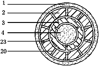
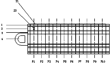
[0019] exist Figure 1 ~ Figure 3 In the shown embodiment of the magnetic lock, the magnetic lock includes an outer magnetic ring 1 , a lock core 2 , a magnetic column 23 , a transmission shaft 3 and a key 4 .

[0020] The outer magnetic ring 1 is a permanent magnet, which is sleeved on the outside of the lock core 2 , and the lock core 2 is an annular column, which is sleeved on the outside of the transmission shaft 3 .

[0021] Such as figure 1 , figure 2 As shown, the lock core 2 in the form of an annular column is divided into 10 flat ring columns 21 in the axial direction, each flat ring column 21 is provided with a slideway 20 radially, and the slideways 20 in each flat ring column 21 The directions are not exactly the same; each of the slideways 20 is respectively provided with a magnetic post 23 that can slide along the slideway 20 ; In this example, if figure 1 As shown, the directions in which each slideway 20 is opened are different, for figure 2 In other wor...


PUM


Abstract

The invention provides a magnetic lockset. The magnetic lockset comprises an outer magnetic ring, magnetic columns, a lock cylinder, a transmission shaft and a key. The outer magnetic ring externally sleeves the lock cylinder which is an annular column externally sleeving the transmission shaft, the lock cylinder in the shape of the annular column is axially divided into N flat annular columns, each flat annular column is internally radially provided with a slide way, and directions of the slide ways in the flat annular columns are not completely uniform; the magnetic columns capable of sliding along the slide ways are arranged in the slide ways respectively; the magnetic columns and the outer magnetic ring follow the law that like poles repel; the key is matched with the inner surface of the transmission shaft and longitudinally partitioned into multiple sections, and section magnets are identical to the magnetic columns in magnetism. The magnetic lockset has the advantages that composition modes of the slide ways in the magnetic lockset is complex, features of the magnetic lockset cannot be seen from the outside, and accordingly the magnetic lockset is less prone to breaking, and abrasion degree and fracture probability of the key can be effectively lowered.

Description

Technical field [0001] The invention relates to the field of hardware appliances, in particular to a safety lock. Background technique [0002] At present, the common lock is the tumbler lock. The principle is to use a plurality of different cylindrical parts to lock the lock cylinder; when the correct key is put in, each lock spring is pushed to the same height, and the lock cylinder is released. In recent years, various structures such as two-way and three-way marbles have appeared. [0003] Its main disadvantage is that the safety performance is not high enough, and it is easy to be cracked according to the internal structure. In addition, the key teeth are easy to wear or break inside, which causes great inconvenience to normal use. Contents of the invention [0004] In view of the above problems, the purpose of the present invention is to provide a magnetic lock, which greatly improves the safety of the lock, and the structural features cannot be seen from the ou...

Claims


Application Information

Patent Timeline
Patent Type & Authority Applications(China)
IPC IPC(8): E05B47/00E05B19/26
Inventor 钱月珍
Owner 钱月珍
Learn More