Flexible drive unit for robot joints with tension and joint position feedback
A technology of robot joints and drive units, which is applied in the direction of manipulators, manufacturing tools, joints, etc., can solve the problems of no stepless two-way locking and safety protection of moving pulley blocks, and the inability to realize tension feedback and full closed-loop control of joints. Excellent performance, simplified joint mechanism, and convenient use
- Summary
- Abstract
- Description
- Claims
- Application Information
AI Technical Summary
Problems solved by technology
Method used
Image
Examples
specific Embodiment approach 1
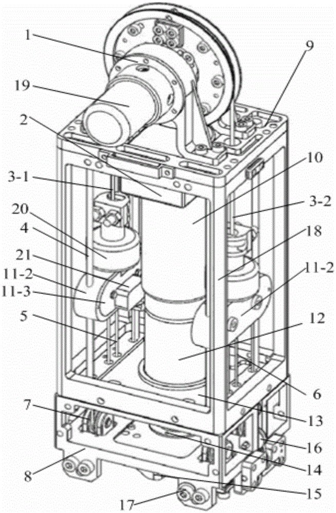
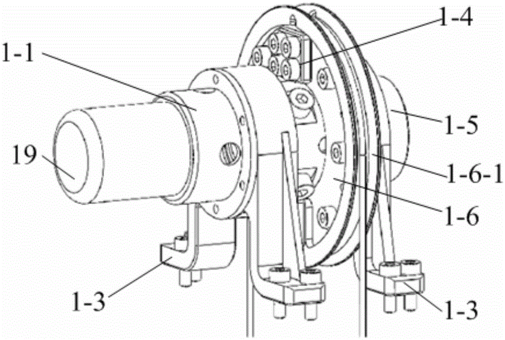
[0018] Specific implementation mode one: combine Figure 1-Figure 8 Explain that the flexible drive unit for robot joints with tension and joint position feedback in this embodiment includes a drive unit frame, a drive device, a transmission device, and an output device 1; the drive unit frame includes a base 8 and an output device fixing plate 9 and drive unit fixed plate 13;
[0019]The drive unit also includes a motor code disc 2, a joint encoder 19, two tension sensors 20 and two limit switches 21;
[0020] The driving device is composed of a servo motor 10, a reducer 12 and an output bushing 14;
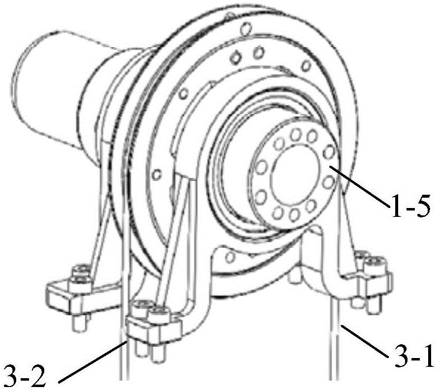
[0021] The transmission device consists of a bottom wire rope two-way locking device 15, two sets of bottom guide fixed pulley devices 7, two side guide fixed pulley devices 16, two movable pulley devices, four cylindrical guide rails for four movable pulley blocks, and a first pulley for the output device. The traction wire rope 3-1, the output device are made of the second t...
specific Embodiment approach 2
[0032] Specific implementation mode two: combination figure 1 and Figure 6 To illustrate, the speed reducer 12 in this embodiment is a planetary speed reducer. In this way, the planetary reducer has the advantages of light weight, high load capacity, large output torque, large speed ratio, long service life and safe and reliable performance, and is suitable for applications such as the hip joint of biped robots. Others are the same as in the first embodiment.
specific Embodiment approach 3
[0033] Specific implementation mode three: combination figure 1 Note that the axis of the servo motor 10 of the driving device of this embodiment is perpendicular to the axis of the output sheave support shaft 1 - 5 of the output device 1 . With such arrangement, the servo motor 10 can make full use of the space between the two movable pulley devices, ensuring that the unit has a compact structure and a smaller volume. Others are the same as in the first or second embodiment.
PUM
 Abstract
Description
Claims
Application Information
 - Generate Ideas
- Intellectual Property
- Life Sciences
- Materials
- Tech Scout
- Unparalleled Data Quality
- Higher Quality Content
- 60% Fewer Hallucinations
Browse by: Latest US Patents, China's latest patents, Technical Efficacy Thesaurus, Application Domain, Technology Topic, Popular Technical Reports.
© 2025 PatSnap. All rights reserved.Legal|Privacy policy|Modern Slavery Act Transparency Statement|Sitemap|About US| Contact US: help@patsnap.com


