Method for reinforcing mixing effect of hydraulic reactor
A mixing effect and reactor technology, applied in chemical instruments and methods, chemical methods for reacting liquids and gaseous media, carbon monoxide reaction to prepare carboxylic acids, etc., can solve the problem of unsatisfactory gas-liquid and liquid-liquid mixing effects, The complex structure of the reactor, etc.
- Summary
- Abstract
- Description
- Claims
- Application Information
AI Technical Summary
Problems solved by technology
Method used
Image
Examples
Embodiment 1
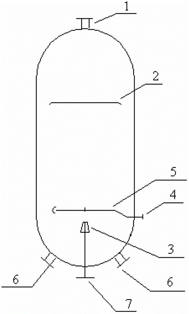
[0019] use figure 1 The hydraulic reactor shown includes an air outlet 1, a baffle 2, a liquid injection device 3, an air inlet 4, a gas distributor 5, a liquid outlet 6, and a liquid inlet 7; wherein, the air inlet 4 is located at the reaction The lower part of the side of the reactor, the gas outlet 1 is located at the top of the reactor, the liquid inlet 7 is located at the bottom of the reactor, and the liquid outlet 6 is symmetrically placed on both sides of the lower head of the reactor; the gas distributor 5 is located between the baffle plate 2 and the liquid injection device 3 The baffle 2 is located below the upper head; the baffle 2 has an air outlet.
[0020] Among them, the distance h between the baffle plate 2 and the gas distributor 5 1 The distance h between the liquid injection device 3 and the gas distributor 5 2 The relationship is: h 2 :h 1 =0.1. The diameter of the reactor is 4000mm, and the diameter of the baffle is 3600mm. The diameter of the air o...
Embodiment 2
[0023] Same as [Example 1], only the distance h1 between the baffle plate 2 and the gas distributor 5 and the distance h between the liquid injection device 3 and the gas distributor 5 2 The relationship is: h 2 :h 1 =0.2. The diameter of the reactor is 4000mm, and the diameter of the baffle is 3400mm. The diameter of the air outlet on the baffle is 5mm. The opening ratio of the baffle is 0.2. The baffle has a skirt, the height of the skirt is 100mm, and the skirt is 30° to the main body of the baffle. The gas distributor is a double-ring gas distributor, with an outer diameter of 2000mm, an inner diameter of 1000mm, and a number of 300 openings, which are equally spaced and evenly distributed. The liquid injection device is a reduced-bore tube type with an inlet diameter of 300mm and an outlet diameter of 150mm.
[0024] The above-mentioned reactor is used in the reaction of synthesizing acetic acid from methanol. The raw material methanol, CO and catalyst are used for...
Embodiment 3
[0026] Same as [Example 1], only the distance h between the baffle plate 2 and the gas distributor 5 1 The distance h between the liquid injection device 3 and the gas distributor 5 2 The relationship is: h 2 :h 1 =0. The diameter of the reactor is 4000mm, and the diameter of the baffle is 3500mm. The diameter of the air outlet on the baffle is 10mm. The opening ratio of the baffle is 0.25. The baffle has a skirt, the height of the skirt is 100mm, and the skirt is 60° to the main body of the baffle. The gas distributor is a double-ring gas distributor, with an outer diameter of 2800mm, an inner diameter of 1800mm, and a number of 300 openings, which are equally spaced and evenly distributed. The liquid injection device is a reduced-bore tube type with an inlet diameter of 300mm and an outlet diameter of 150mm.
[0027] The above-mentioned reactor is used in the reaction of synthesizing acetic acid from methanol. The raw material methanol, CO and catalyst are used for o...
PUM
 Abstract
Description
Claims
Application Information
 - R&D
- Intellectual Property
- Life Sciences
- Materials
- Tech Scout
- Unparalleled Data Quality
- Higher Quality Content
- 60% Fewer Hallucinations
Browse by: Latest US Patents, China's latest patents, Technical Efficacy Thesaurus, Application Domain, Technology Topic, Popular Technical Reports.
© 2025 PatSnap. All rights reserved.Legal|Privacy policy|Modern Slavery Act Transparency Statement|Sitemap|About US| Contact US: help@patsnap.com

