Micromechanical structure with deformable diaphragm and protection part with strong resistance to deformation

A technology of micromachines and diaphragms, which is applied in the directions of microstructure devices, microstructure technology, and microstructure devices composed of deformable elements, which can solve the problems of easy damage, breakage, and structural cracking of diaphragms.

Active Publication Date: 2016-03-09
AUXITROL
View PDF5 Cites 2 Cited by
  • Summary
  • Abstract
  • Description
  • Claims
  • Application Information

AI Technical Summary

Problems solved by technology

[0007] These diaphragms subjected to higher energies become vulnerable, their intrinsic properties are altered and their structure may crack or even break

Method used


Image

  • Micromechanical structure with deformable diaphragm and protection part with strong resistance to deformation
  • Micromechanical structure with deformable diaphragm and protection part with strong resistance to deformation
  • Micromechanical structure with deformable diaphragm and protection part with strong resistance to deformation

Examples


Embodiment Construction

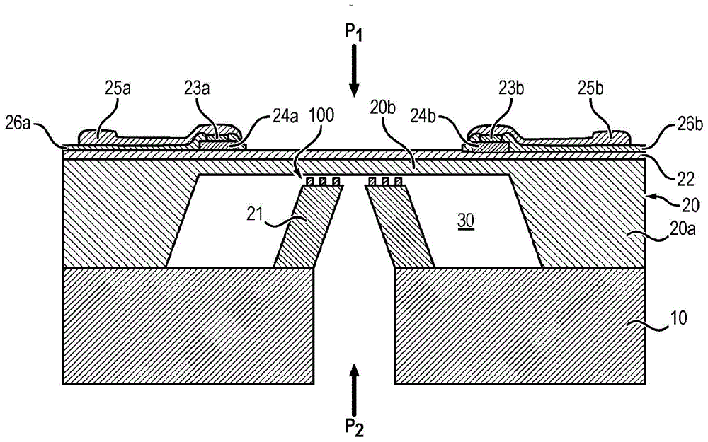
[0038] The micromechanical mechanism is intended to measure or detect mechanical or dynamic quantities such as pressure, said micromechanical mechanism comprising a deformable diaphragm 20 and a support substrate 10 .

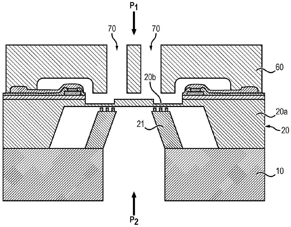
[0039] as in figure 1 , figure 2 and Figure 4 As shown in , the diaphragm is arranged on the support substrate 10 to define a free space 30 . In the case of a micromechanical mechanism for differential pressure measurement, this free space 30 is intended to be filled with a fluid. In this case, the pressure P1 comes from above the structure and the pressure P2 comes from below the structure (see figure 1 , figure 2 and Figure 4 ).

[0040] The diaphragm 20 is intended to support the pressure measuring cells 22, 23a, 23b, 24a, 24b, 25a, 25b, 26a, 26b.

[0041] Free space 30 is typically formed in the initial substrate by micromachining. The micromachining technique used to form such free spaces may be, for example, chemical etching, eg KOH etching at...


PUM

PropertyMeasurementUnit
thicknessaaaaaaaaaa
heightaaaaaaaaaa
heightaaaaaaaaaa

Abstract

The invention relates to a micromechanical mechanism for measuring or detecting mechanical or dynamic quantities, comprising a deformable diaphragm (20) and a support substrate (10), said diaphragm (20) comprising a first part (20a) and a second portion (20b) surrounded by said first portion (20a), said second portion (20b) having a thickness smaller than that of said first portion (20a), said diaphragm (20) being suspended on said above the support substrate (10) and thus define a free space (30), the micromechanical mechanism additionally comprises a lower abutment seat (21) for confining the membrane Deformation of the sheet (20), the lower abutment seat (21) is arranged on the support substrate (10) and extends from the support substrate (10) towards the diaphragm (20) to the free In the space (30), it is characterized in that the lower adjoining support (21) includes an island (101-108), and the island (101-108) is formed from the lower abutting support (21) A flat surface extends into said free space (30) towards the membrane (20), said islands (101-108) forming a relief structure in such a way that in said islands (101-108) In the case of contact with the fine part (20b) of the diaphragm (20), the contact surface between the islands (101-108) and the fine part (20b) of the diaphragm (20) is relatively ) of the fine portion (20b) is smaller in size.

Description

technical field [0001] The invention relates to a micromechanical structure intended to measure or detect mechanical or dynamic quantities. [0002] And more particularly, the present invention relates to a micromechanical structure for absolute, relative, or differential pressure measurement of pressure. Background technique [0003] A micromechanical mechanism for measuring a mechanical or dynamic quantity such as pressure, generally comprising a deformable diaphragm suspended above the supporting substrate and defining a free space, and a support substrate. [0004] The use of these suspended membranes is known. [0005] Capacitive sensors or strain gauges supported by the diaphragm are capable of measuring the deformation experienced by the diaphragm subjected to external energy (e.g. pressure applied perpendicular to the main plane of the diaphragm). [0006] The energy applied to the diaphragm or the change of the force applied to the diaphragm can for example be me...

Claims


Application Information

Patent Timeline
Patent Type & Authority Patents(China)
IPC IPC(8): G01L9/00G01L19/06
CPCG01L9/0042G01L19/0618B81B2201/0264B81B3/0051G01L9/0048B81B3/0097G01L9/0047
Inventor S·布里达
Owner AUXITROL
Why Eureka
Try Eureka