
Auto-positioning device for visual inspection of exterior body panels

A technology for visual inspection and outer cover, applied in the field of workpiece automation fixtures, can solve the problems of narrow detection range, low precision, slow detection speed, etc., and achieve the effect of fast positioning speed, high precision and improved detection efficiency

Inactive Publication Date: 2016-05-18
JILIN UNIV
View PDF8 Cites 0 Cited by
  • Summary
  • Abstract
  • Description
  • Claims
  • Application Information

AI Technical Summary

Problems solved by technology

[0005] The technical problem to be solved by the present invention is to change the problems of slow, low precision and narrow detection range of traditional manual detection in industrial production, and to provide an automatic positioning device for visual detection of automobile body outer coverings

Method used


Image

  • Auto-positioning device for visual inspection of exterior body panels
  • Auto-positioning device for visual inspection of exterior body panels
  • Auto-positioning device for visual inspection of exterior body panels

Examples


Embodiment Construction

[0037] The present invention is described in detail below in conjunction with accompanying drawing:

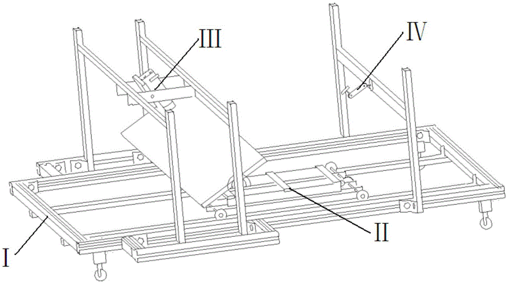
[0038] refer to figure 2 , The auto-positioning device for visual detection of the outer cover of the automobile according to the present invention is composed of a base I, a power unit II, an image acquisition system III, and a laser emitter assembly IV. The base I is the assembly base of the automatic positioning device for the visual inspection of the entire automobile outer cover, the power device II is installed on the power guide rail of the base I, and the image acquisition system III and the laser transmitter assembly IV are respectively installed on the bottom of the base I. on the brackets on the left and right sides.

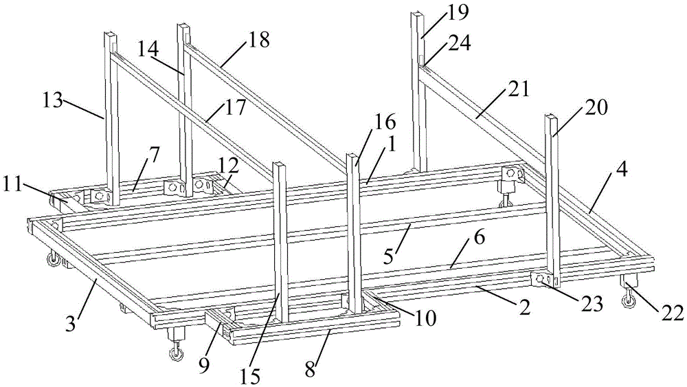
[0039] refer to image 3 and Figure 10 , the base I includes a pedestal, an image acquisition system bracket, a laser transmitter assembly bracket, 32 wide-angle irons 23 with the same structure and 16 narrow-angle irons 24 with the same structur...


PUM

PropertyMeasurementUnit
lengthaaaaaaaaaa
lengthaaaaaaaaaa

Abstract

The invention discloses automatic positioning equipment for visual inspection of car body covering parts for solving the problems that the traditional manual detection speed is low, the precision is low and the detection range is narrow. The automatic positioning equipment comprises a base, a power device, an image acquisition device and a laser transmitter assembly, wherein the base comprises a base frame, an image acquisition system support and a laser transmitter assembly support, the lower ends of a camera height adjustment pole 1 and a camera height adjusting pole 2 of the image acquisition system support are fixedly connected with the base frame, the lower ends of a camera height adjustment pole 3 and a camera height adjusting pole 4 of the image acquisition system support are fixedly connected with the base frame, the lower ends of a laser height adjustment pole 1 and a laser height adjusting pole 2 of the laser transmitter assembly support are fixedly connected with the outer sides of a length control rod 1 and a length control rod 2 of the base frame, the power device is arranged on a power guide rail 1 and a power guide rail 2 of the base frame, the image acquisition device is arranged on the image acquisition system support and the laser transmitter assembly is arranged on the laser transmitter assembly support.

Description

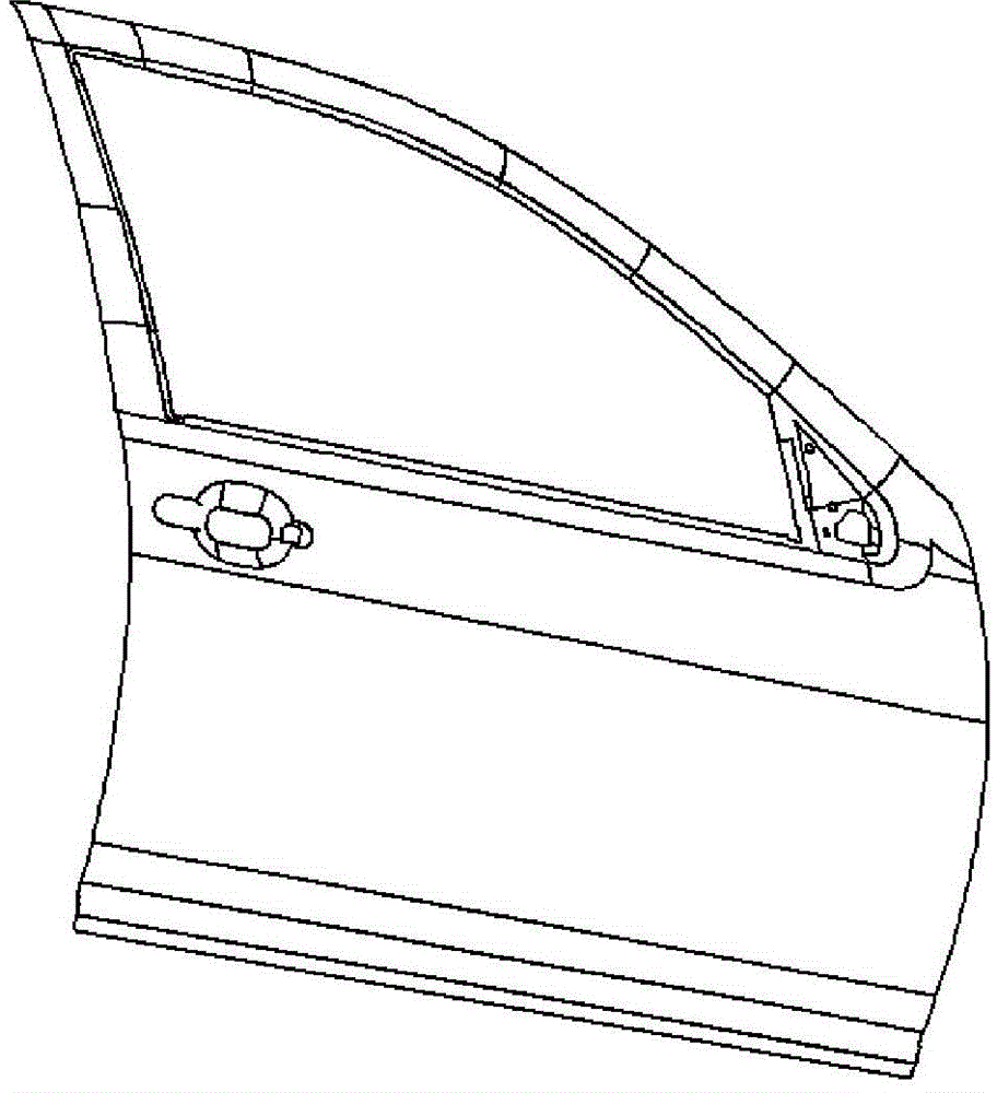
technical field [0001] The invention relates to an automatic workpiece fixing device in the field of computer vision detection, more specifically, the invention relates to an automatic positioning device applied to the visual detection of the outer cover of an automobile body. Background technique [0002] As the main means of transportation for people's daily travel, automobiles are not only responsible for carrying functions, but also a handicraft that integrates art and beauty. The equipment and methods used in paint film quality inspection have a decisive effect on the accuracy and speed of car body paint film defect detection. [0003] refer to figure 1 , shown in the figure is the front view of a car door outer panel. At present, most of the car outer panels are detected by manual visual inspection, but manual inspection cannot accurately detect the small differences in car body paint film defects. In addition, the various types of paint film defects and the differen...

Claims


Application Information

Patent Timeline
Patent Type & Authority Patents(China)
IPC IPC(8): G01N21/49G01N21/88
Inventor 崔岸陈洪柱骆亚微张士展徐文强冯冲徐丽娟
Owner JILIN UNIV
Learn More