
Air-cooled brake wheel

A brake wheel, air-cooled technology, applied in the direction of the brake type, brake components, hoisting device, etc., can solve the problems of affecting the braking effect, the temperature rise of the brake wheel surface, etc., and achieve reliable design principles and acceleration loss Speed, the effect of highlighting substantive features

Inactive Publication Date: 2014-09-03
JIGANG GRP
View PDF7 Cites 2 Cited by
  • Summary
  • Abstract
  • Description
  • Claims
  • Application Information

AI Technical Summary

Problems solved by technology

[0006] The object of the present invention is to provide and design an air-cooled brake wheel for the above-mentioned defects in the prior art that the surface temperature of the brake wheel cannot be dissipated quickly and cause its surface temperature to rise sharply, thereby affecting the braking effect and causing potential safety hazards. Dissipate the heat generated by the brake wheel during the braking process, and at the same time improve the braking effect of the brake wheel and eliminate potential safety hazards

Method used


Image

  • Air-cooled brake wheel
  • Air-cooled brake wheel
  • Air-cooled brake wheel

Examples


Embodiment Construction

[0023] The present invention will be described in detail below with reference to the accompanying drawings and specific embodiments. The following embodiments are explanations of the present invention, but the present invention is not limited to the following embodiments.

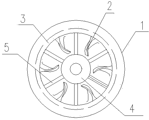
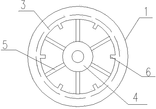
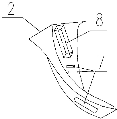
[0024] like Figures 1 to 4 As shown, an air-cooled brake wheel provided by the present invention includes a brake wheel body and cooling blades 2, and the brake wheel body includes a hub 1, a bearing sleeve 4 and a spoke 5 connecting the hub 1 and the bearing sleeve 4 , the heat dissipation blades 2 are fixed on the inner peripheral surface of the hub 1, an annular cavity 3 is arranged in the hub 1, and a group of circular through holes are uniformly arranged on the inner peripheral surface of the hub 1, and the circular through holes are arranged on the inner peripheral surface of the hub 1. The hole communicates with the annular cavity 3 in the hub 1, the heat dissipation blade 2 is provided with a hollo...


PUM


Abstract

The invention relates to an air-cooled brake wheel. The air-cooled brake wheel comprises a brake wheel body and a heat dissipating blade. The brake wheel body comprises a hub, a bearing bush and a spoke connecting the hub and the bearing bush. The heat dissipating blade is fixed on the inner circumference face of the hub. The hub is internally provided with an annular cavity, and a set of circular through holes are evenly formed in the inner circumference face of the hub, and communicated with the annular cavity in the hub. The heat dissipating blade is internally provided with a hollow cavity which is communicated with the annular cavity in the hub through the circular through holes in the inner circumference face of the hub, and the annular cavity in the hub and the hollow cavity in the heat dissipating blade are filled with cooling liquid. Heat is dissipated to the hollow cavity in the heat dissipating blade through flowing of the cooling liquid, the heat dissipating blade rotates along with the rotation of the hub, flow air is produced between the hub and the bearing bush and can bring the heat produced by the friction of the hub away and dissipate the heat of the cooling liquid in the hollow cavity, the heat dissipation of the surface of the hub is accelerated, and the heat dissipating effect is improved.

Description

technical field [0001] The invention belongs to the technical field of mechanical brake equipment, and relates to a brake wheel, in particular to an air-cooled brake wheel. Background technique [0002] All mechanical equipment such as cranes and hoists need to be equipped with braking devices. The brake wheels are held tightly by the brake shoes of the brakes, and the brakes are implemented by the strong friction between the brake shoes and the brake wheels. [0003] During the braking process, since the brake wheel is installed at the high-speed running end of the mechanical equipment, the speed is often above 1000r / min, so high-speed friction will inevitably lead to a sharp rise in the surface temperature of the brake wheel. Under normal conditions, the surface temperature of the brake wheel can reach 600°C, or even higher. Such a high temperature will not only reduce the surface hardness and deformation of the brake wheel, but also cause the abnormal wear of the brake wh...

Claims


Application Information

Patent Timeline
IPC IPC(8): F16D65/80F16D65/807B66D5/08
Inventor 黄一声张文周刘伟管延科田常松
Owner JIGANG GRP
Learn More