Construction method of a shear wall concrete formwork
A technology of concrete formwork and construction method, which is applied in formwork/formwork/work frame, processing of building materials, preparation of building components on site, etc., can solve problems such as low construction efficiency, and achieve improved construction efficiency and high splicing efficiency. , the use of high efficiency
- Summary
- Abstract
- Description
- Claims
- Application Information
AI Technical Summary
Problems solved by technology
Method used
Image

Examples
Embodiment 1
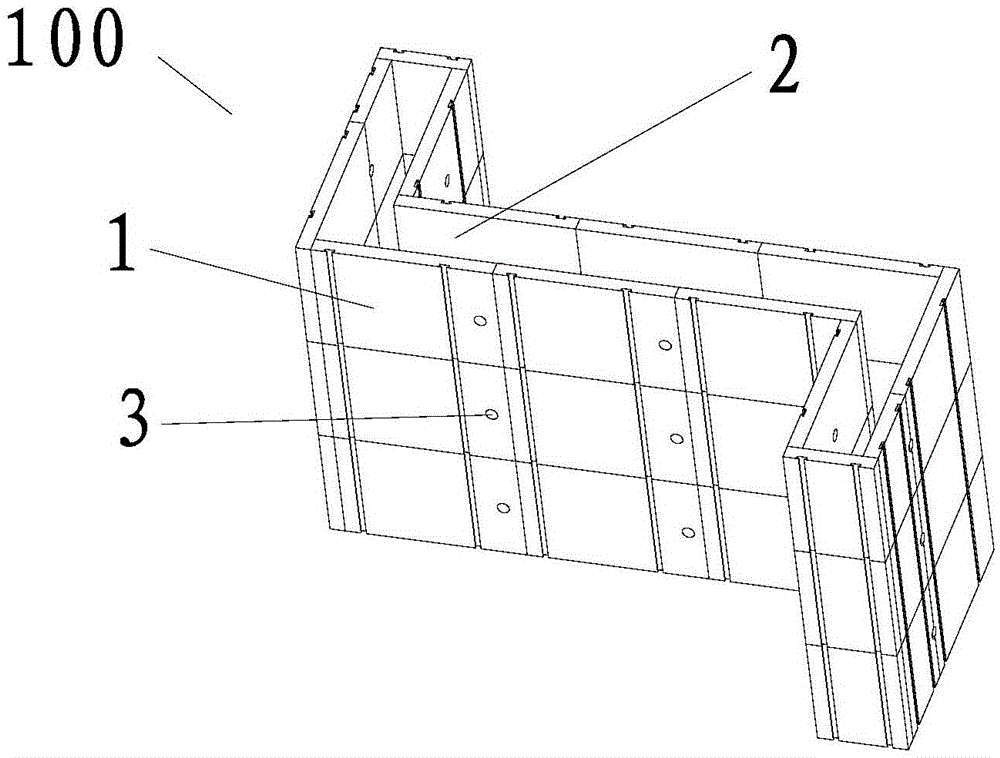
[0072] The construction method of the shear wall concrete formwork provided by the present embodiment comprises the following steps:
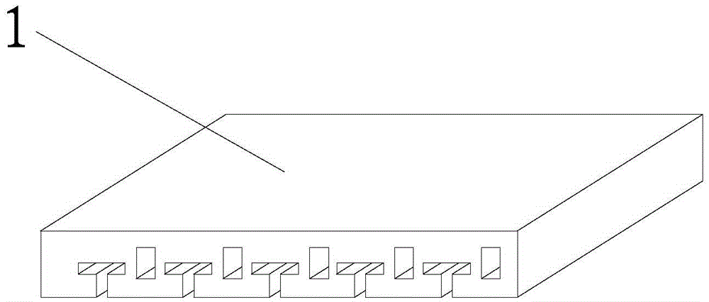
[0073] S1: Stitching templates, such as figure 1 As shown, the standardized concrete formwork 1 is spliced into a pre-designed shear wall formwork 100. The concrete formwork 1 can be a concrete formwork in the prior art, but it needs to be ensured that one side is a smooth surface, which is compatible with the concrete when pouring concrete grout. The slurry contacts and forms the surface of the condensed building component, and the other surface needs to be provided with quick-connect grooves or similar structures so that various fixtures can be installed. The concrete formwork 1 used in this embodiment is a Chinese utility model patent ZL201220200056. 8 disclosed concrete formwork, its structure is as figure 2 As shown, the size can be set according to actual needs. The shear wall formwork 100 is closed, and its closed interior forms a c...
Embodiment 2
[0089]The difference between this embodiment and Embodiment 1 is that in step S3, the gap in the horizontal direction between the concrete forms 1 on the same plane is also adjusted, and the adjustment method includes the following steps:
[0090] a. In step S3, after installing the horizontal fixed pipe 5, ensure that the horizontal fixed pipe 5 can move along its length direction under a predetermined force. The specific installation method is to lock the horizontal fixed pipe 5 on the concrete with the screw 6 On the formwork 1, properly control the locking force of the screw 6 so that it will not lock the horizontal fixing pipe 6 and the concrete formwork 1 too tightly. Move, the installation hole that is used for locking screw 6 on the horizontal fixed pipe 5 needs to be slightly larger than the outer diameter of screw 6, preferably be designed as the waist-shaped hole that the longitudinal direction is consistent with the horizontal fixed pipe 5 lengthwise. In addition, ...
Embodiment 3
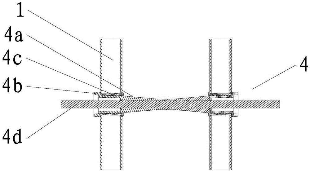
[0097] The difference between this embodiment and Embodiment 1 is that the concrete formwork 1 used in this embodiment is further improved on the basis of the concrete formwork disclosed in Chinese utility model patent ZL201220200056.8, which is disclosed in Chinese utility model patent ZL201220200056. In 8, the splicing surface of the concrete formwork 1 and its smooth surface are perpendicular to each other, that is, there is an angle of 90° between them. It is not convenient to disassemble after pouring concrete, and a large disassembly force is required. In this embodiment, the angle between the joint surface of the concrete formwork 1 and its smooth surface is changed from 90° to 45°. Those skilled in the art can also design the clamps of only part of the splicing surface of the concrete formwork 1 and its smooth surface to be 45° according to the actual dismounting force, and the other splicing surfaces are still at an angle of 90°.
[0098] When using the concrete formw...
PUM
 Abstract
Description
Claims
Application Information
 - R&D
- Intellectual Property
- Life Sciences
- Materials
- Tech Scout
- Unparalleled Data Quality
- Higher Quality Content
- 60% Fewer Hallucinations
Browse by: Latest US Patents, China's latest patents, Technical Efficacy Thesaurus, Application Domain, Technology Topic, Popular Technical Reports.
© 2025 PatSnap. All rights reserved.Legal|Privacy policy|Modern Slavery Act Transparency Statement|Sitemap|About US| Contact US: help@patsnap.com