
Laser-TOPTIG hybrid welding method

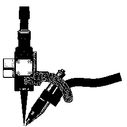
A hybrid welding and laser technology, which is applied in the field of laser-TOPTIG composite welding, can solve the problems that limit the popularization and application of laser-TIG composite wire filling welding methods, limit the flexibility and accessibility of robots, and cannot strictly guarantee the accuracy of wire feeding, etc. problem, to achieve the effect of improving flexibility and accessibility, improving positioning accuracy and stability, and growing stable

Active Publication Date: 2014-09-03
HARBIN INST OF TECH
View PDF6 Cites 13 Cited by
  • Summary
  • Abstract
  • Description
  • Claims
  • Application Information

AI Technical Summary

Problems solved by technology

[0004] 1. The TIG welding torch and wire feeding device are fixed on the laser head through a fixture, which cannot strictly guarantee the accuracy of wire feeding, so that the quality of the weld cannot be guaranteed;
[0005] 2. The position of the tungsten electrode and the wire feeding nozzle is very sensitive, so that the feeding angle and position of the welding wire have a great influence on the formation, growth, and transition of the droplet, thus affecting the stability of the welding process;
[0006] 3. The TIG welding gun and wire feeding device are fixed on the laser head, which increases the volume of the laser working head and limits the flexibility and accessibility of the robot;
[0009] These shortcomings limit the popularization and application of the laser-TIG composite filler wire welding method.

Method used


Image

  • Laser-TOPTIG hybrid welding method
  • Laser-TOPTIG hybrid welding method
  • Laser-TOPTIG hybrid welding method

Examples


specific Embodiment approach 1

[0032] Specific embodiment one: the method for a kind of laser-TOPTIG composite welding of the present embodiment, concrete operation is as follows:

[0033] Step 1: Before welding, grind or clean the surface of the workpiece to be welded, and fix the polished or cleaned workpiece to be welded on the welding fixture;

[0034] Step 2: Apply the laser and TOPTIG welding together on the area to be welded, and set the geometric parameters: the diameter of the spot is 0.1~0.5mm, and the defocus is -3~﹢3mm;

[0035] Step 3: Set the welding parameters of laser-TOPTIG hybrid welding: the arc current is 50-400A, the angle between the welding torch and the vertical direction is 25°-55°, the welding speed is 50-500mm / min, and the wire feeding speed is 50-600mm / min, the angle between the welding wire and the extension line of the tungsten electrode is 15°~30°, and the shielding gas is an inert gas;

[0036] Step 4: Start the control switch, first pass in the shielding gas, and then igni...

specific Embodiment approach 2

[0047] Embodiment 2: This embodiment differs from Embodiment 1 in that: the droplet transfer forms of the welding wire melting in TOPTIG welding are divided into continuous contact transfer and droplet transfer. Others are the same as in the first embodiment.

specific Embodiment approach 3

[0048] Embodiment 3: This embodiment differs from Embodiment 1 or Embodiment 2 in that: the wire feeding speed of the welding wire in the continuous contact transition is greater than that in the drop transition. Others are the same as in the first or second embodiment.


PUM

PropertyMeasurementUnit
Diameteraaaaaaaaaa

Abstract

The invention relates to a laser-TOPTIG hybrid welding method. The laser-TOPTIG hybrid welding method includes the following steps: firstly, polishing or cleaning the surface of a workpiece to be welded, and installing a clamp; secondly, setting geometrical parameters; thirdly, setting welding parameters of laser-TOPTIG hybrid welding; fourthly, turning on a control switch, leading in shielding gas, then igniting an electric arc, emitting lasers after 1.0 s to 2.0 s, feeding a welding wire to the area at the highest temperature under mutual effects of laser beams and the electric arc, and then moving a laser device and a welding gun together to carry out laser-TIG electric arc welding. By means of the welding method, an operational program is simplified, efficiency is improved, the welding accuracy and the welding stability are guaranteed, and the welded joint quality is improved.

Description

technical field [0001] The invention relates to a laser-TOPTIG composite welding method, which belongs to the field of material processing engineering. Background technique [0002] As we all know, laser-arc hybrid welding, as a new modern laser welding method, has unique advantages: ①High efficiency and energy saving; ②Increased weld penetration and stable welding arc; ③Improved welding adaptability and high-speed welding; ④By adjusting the energy matching of the two heat sources, the weld formation is improved. In the hybrid welding process, the laser heat source mainly includes CO 2 Laser, YAG laser, fiber laser, etc. The object of compounding can be TIG, MIG or plasma arc, etc.; the compounding methods include coaxial compounding, paraxial compounding, and even multi-electrode and single laser compounding. At present, laser arc hybrid welding has been used in shipbuilding, automobile, petrochemical and other fields, showing good application potential. In the hybrid we...

Claims


Application Information

Patent Timeline
IPC IPC(8): B23K26/348B23K26/60
CPCB23K26/348
Inventor 雷正龙刘鸣陈彦宾胡雪杨雨禾陈曦吴艺超张芙蓉黄乐
Owner HARBIN INST OF TECH
Learn More