illuminator
A technology of illuminators and sub-reflectors, which is applied in the field of illuminators, can solve problems such as the difficulty of light-guiding reflectors, and achieve the effect of improving visibility
- Summary
- Abstract
- Description
- Claims
- Application Information
AI Technical Summary
Problems solved by technology
Method used
Image

Examples
no. 1 Embodiment approach
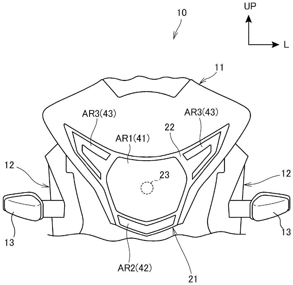
[0039] figure 1 It shows the front view of the two-wheeled motorcycle equipped with the headlight illuminator which concerns on 1st Embodiment of this invention.
[0040] The motorcycle 10 has a front cover 11 covering the front of the vehicle body, and a front side cover 12 formed of a pair of left and right sides provided on the front cover 11 and covering the left and right sides of the front of the vehicle body. A single headlight illuminator 21 that illuminates the front of the vehicle body is provided at an intermediate position in the vehicle width direction of the front cover 11 , and turn signal lamp units 13 are provided on the left and right front side covers 12 , respectively.
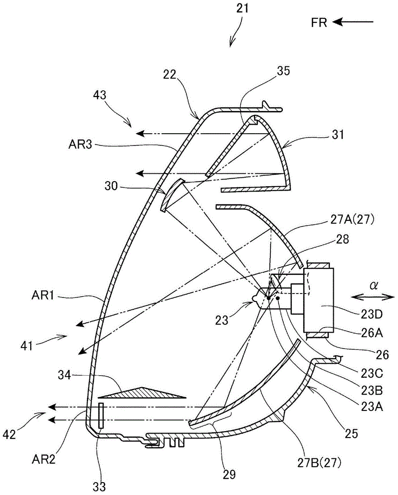
[0041] The front illuminator 21 has: a front surface lens 22 covering the front surface of the illuminator 21; and a lamp cover 25 located behind the front surface lens 22 and supporting a single bulb 23 formed as a light source on the lamp cover 25. and between the front surface lens 22. ...
no. 2 Embodiment approach
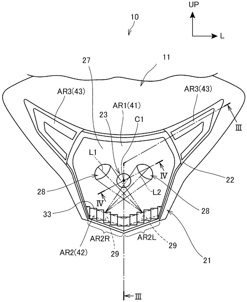
[0099] Figure 5 It is a front view showing the front illuminator 21 and its peripheral structure of the second embodiment. In this figure, with the above figure 2 Likewise, the middle region of the front lens 22 (the region corresponding to the middle region AR1 ) is removed. in addition, Figure 6 means along Figure 5 A cross-sectional view cut along line VI-VI. In addition, in Figure 5 , Figure 6In each figure described below and below, the same structures as those of the first embodiment are denoted by the same symbols, and only the different parts will be described here.
[0100] Such as Figure 5 and Figure 6 As shown, in the second embodiment, the left and right first sub-reflectors 28 are located behind the bulb 23, and are arranged in an area where the light emitted backward by the bulb 23 (filament 23A for low beam) can be irradiated, and form a It is a shape that can be released from the mold in the front-rear direction α, and it faces the opening 27K ...
no. 3 Embodiment approach
[0116] Figure 7 It is a side view showing the front illuminator 21 and its peripheral structure of the third embodiment. In the third embodiment, a case where the first sub-mirror 28 is integrally formed with the movable mirror-type main mirror 27 will be described. In this configuration, the first sub-mirror 28 and the second sub-mirror 29 are integrally provided with the main mirror 27, which is a movable movable mirror capable of adjusting the optical axis.
[0117] The position of the swing axis 27J of the main mirror 27 is set such that the positions of both the first and second sub mirrors 28 and 29 are moved to appropriate positions corresponding to the position change of the main mirror 27 . In this structure, by setting the swing shaft 27J at Figure 7 The position shown (located above the first sub-reflector 28 and behind the main reflector 27), when the main reflector 27 is moved to adjust the optical axis of the main light-emitting part 41, the first sub-reflect...
PUM
 Abstract
Description
Claims
Application Information
 - R&D
- Intellectual Property
- Life Sciences
- Materials
- Tech Scout
- Unparalleled Data Quality
- Higher Quality Content
- 60% Fewer Hallucinations
Browse by: Latest US Patents, China's latest patents, Technical Efficacy Thesaurus, Application Domain, Technology Topic, Popular Technical Reports.
© 2025 PatSnap. All rights reserved.Legal|Privacy policy|Modern Slavery Act Transparency Statement|Sitemap|About US| Contact US: help@patsnap.com