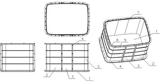
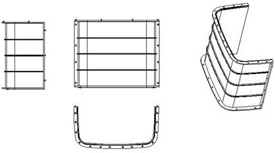
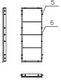
Plastic electric cable well
A technology for cable wells and plastics, applied in the field of cable wells made of polyoxymethylene-based toughened modified materials, to achieve the effect of reducing replacement costs and maintenance costs
- Summary
- Abstract
- Description
- Claims
- Application Information
AI Technical Summary
Problems solved by technology
Method used
Image
Examples
Embodiment 1
[0035] 100 parts of polyoxymethylene resin, 30 parts of composite modified particles, 8 parts of ethylene bisstearamide, 0.5 parts of formaldehyde absorbent, and 0.2 parts of antioxidant.
[0036] The composite modified particles are composed of silicon carbide wafers, nano-calcium carbonate particles, lead powder particles and binders, and the nano-calcium carbonate particles and lead powder particles are bonded on the silicon carbide wafers through binders; wherein, the carbonized 10 parts of silicon wafer, 5 parts of nano calcium carbonate, 10 parts of lead powder, 5 parts of binder.
[0037] The binder is fatty acid zinc; the antioxidant is tetrakis[β-(3,5-di-tert-butyl-4-hydroxyphenyl) propionate] pentaerythritol ester.
[0038] Prepare the composite particle modified polyoxymethylene resin material according to the following steps:
[0039] ① Soften or partially melt the binder at a temperature higher than 60°C and lower than 160°C to form a film on the surface of the s...
Embodiment 2
[0044] 120 parts of polyoxymethylene resin, 50 parts of composite modified particles, 14 parts of ethylene bis stearamide, 0.9 parts of formaldehyde absorbent, and 0.6 parts of antioxidant.
[0045] The composite modified particles are composed of silicon carbide wafers, nano-calcium carbonate particles, lead powder particles and binders, and the nano-calcium carbonate particles and lead powder particles are bonded on the silicon carbide wafers through binders; wherein, the carbonized 20 parts of silicon wafer, 10 parts of nano calcium carbonate, lead powder 15 parts, 5 parts of binder.
[0046] The binder is fatty acid magnesium; the antioxidant is β-(4-hydroxyphenyl-3,5-di-tert-butyl) n-octadecyl propionate.
[0047] Process step is with embodiment 1.
Embodiment 3
[0049] 110 parts of polyoxymethylene resin, 40 parts of composite modified particles, 10 parts of ethylene bis stearamide, 0.8 parts of formaldehyde absorbent, and 0.5 parts of antioxidant.
[0050] The composite modified particles are composed of silicon carbide wafers, nano-calcium carbonate particles, lead powder particles and a binder, and the nano-calcium carbonate particles and lead powder particles are bonded to the silicon carbide wafer by the binder; wherein, the silicon carbide 20 parts of chips, 5 parts of nano-calcium carbonate, 10 parts of lead powder, and 5 parts of binder.
[0051] The binder is selected from fatty acid calcium. The antioxidant is selected from tetrakis[β-(3,5-di-tert-butyl-4-hydroxyphenyl)propionate]pentaerythritol esters.
PUM
 Abstract
Description
Claims
Application Information
 - R&D
- Intellectual Property
- Life Sciences
- Materials
- Tech Scout
- Unparalleled Data Quality
- Higher Quality Content
- 60% Fewer Hallucinations
Browse by: Latest US Patents, China's latest patents, Technical Efficacy Thesaurus, Application Domain, Technology Topic, Popular Technical Reports.
© 2025 PatSnap. All rights reserved.Legal|Privacy policy|Modern Slavery Act Transparency Statement|Sitemap|About US| Contact US: help@patsnap.com


