
Vacuum Filtration Combined Electric Dewatering Sludge Treatment System

A sludge treatment and electric dehydration technology, which is applied in the direction of dehydration/drying/thickened sludge treatment, etc., can solve the problems of low operation efficiency, poor dehydration effect, high treatment cost, etc.

Inactive Publication Date: 2015-10-28
邓立新
View PDF3 Cites 0 Cited by
  • Summary
  • Abstract
  • Description
  • Claims
  • Application Information

AI Technical Summary

Problems solved by technology

The traditional sludge dewatering technology mainly uses plate-and-frame or belt-type or stacked-screw-type or centrifugal-type dewatering machines to dewater sludge mechanically. The disadvantages are: 1) Low operating efficiency, and it is impossible to treat a large amount of sewage at the same time. 2) The dehydration effect is poor, and the moisture content of the sludge after dehydration is still maintained at about 80%; 3) The cost of dehydration is high, not only to purchase a large number of expensive mechanical equipment, but also during the dehydration process. consumes a lot of energy
According to the characteristics of extremely low permeability and high organic matter content of sludge, as well as the principles and characteristics of vacuum filtration dehydration and electric dehydration treatment technology, the dehydration effect of sludge dehydration treatment using vacuum filtration dehydration or electric dehydration treatment technology is average; However, the combination of vacuum filtration dehydration or electric dehydration treatment technology and mechanical dehydration technology can significantly improve the dehydration effect of sludge treatment, but the treatment cost is higher than that of mechanical dehydration technology alone, and its economy is worse.

Method used


Image

  • Vacuum Filtration Combined Electric Dewatering Sludge Treatment System
  • Vacuum Filtration Combined Electric Dewatering Sludge Treatment System

Examples


Embodiment Construction

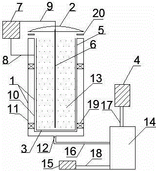
[0026] Below in conjunction with embodiment and attached figure 1 or attached figure 2 The specific implementation of the product technology of the vacuum filtration combined with electric dewatering sludge treatment system disclosed in the present invention is further described.

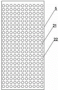
[0027]According to the technical solution of the present invention, the vacuum filtration combined electric dewatering sludge treatment system includes a double-layer vacuum dehydration barrel 1, a barrel cover 2, a filter bag 3, a vacuum pump 4, a cathode discharge electrode 5, an anode discharge electrode 6, a power supply 7, and a cable 8. Cable 2 9. The double-layer vacuum dehydration barrel 1 is a double-layer barrel structure formed by the combination of the inner barrel body 10 and the outer layer barrel body 11, and the barrel mouth of the inner layer barrel body 10 and the barrel mouth of the outer layer barrel body 11 are closed so that Inner layer barrel 10 and outer layer barrel 11 ar...


PUM

PropertyMeasurementUnit
diameteraaaaaaaaaa
heightaaaaaaaaaa

Abstract

A vacuum filtration-electric dehydration combined sludge treatment system includes a double-layer vacuum dehydration barrel, a barrel cover, a filter bag, a vacuum pump, a cathode discharge electrode, an anode discharge electrode, a power supply, a first cable, and a second cable. The disclosed technical scheme of the invention comprises the double-layer vacuum dehydration barrel, the barrel cover, the filter bag and the vacuum pump are used as a vacuum filtration dehydration system for performing vacuum filtration dehydration treatment on sludge; and at the same time, the cathode discharge electrode, the anode discharge electrode, the power supply, the first cable and the second cable are used as an electric dehydration system for performing electric dehydration treatment on the sludge; and the vacuum filtration-electric dehydration combined sludge treatment system has the advantages of low equipment and operation costs, high treatment efficiency and good treatment effect, and can achieve simultaneous treatment of a large amount of sludge.

Description

technical field [0001] The invention relates to a sludge treatment technology in the environmental protection industry, in particular to a product technology of a vacuum filtration combined with electric dehydration sludge treatment system. Background technique [0002] Sludge dehydration treatment is an important task in the environmental protection industry. How to dehydrate a large amount of sludge generated in the process of treating industrial sewage and municipal sewage in an efficient, energy-saving and environmentally friendly manner has always been a major technical issue in the environmental protection industry. The traditional sludge dewatering technology mainly uses plate-and-frame or belt-type or stacked-screw-type or centrifugal-type dewatering machines to dewater sludge mechanically. The disadvantages are: 1) Low operating efficiency, and it is impossible to treat a large amount of sewage at the same time. 2) The dehydration effect is poor, and the moisture c...

Claims


Application Information

Patent Timeline
Patent Type & Authority Patents(China)
IPC IPC(8): C02F11/12
Inventor 邓立新
Owner 邓立新
Learn More