
Brake control system of multi-wheel-train brake machine wheel

A brake control and multi-wheel train technology, applied in the field of brake systems, can solve the problems of heavy system weight, non-wireless brake control, difficult installation, etc., achieve system weight and cost reduction, prevent aircraft brake deviation, and reduce the number of components Effect

Active Publication Date: 2014-08-27
XIAN AVIATION BRAKE TECH
View PDF7 Cites 29 Cited by
  • Summary
  • Abstract
  • Description
  • Claims
  • Application Information

AI Technical Summary

Problems solved by technology

[0004] In September 2012, the article "Research on Civil Aircraft Hydraulic Braking System Architecture" in "Fluid Transmission and Control" summarized the technology of the active aircraft braking system and disclosed three hydraulic architectures of the braking system. Among them: the technical characteristics of system A are mechanical control, Hydraulic actuation, its shortcomings are mainly brake control non-electric transmission, backward technology, heavy system weight, and difficult installation; the technical characteristics of system B are telex and hydraulic actuation, its main shortcomings are many products and system weight Heavy; the technical characteristics of system C are electric transmission and hydraulic actuation, and its shortcomings are mainly due to the large number of products, heavy system weight, and low system utilization
At the same time, the safety design of the electrical architecture of the brake system is not carried out in the three systems. Since the reliability of electrical products is often much lower than that of mechanical products, electrical products in the system often become a weak link that affects system safety in actual use.

Method used


Image

  • Brake control system of multi-wheel-train brake machine wheel
  • Brake control system of multi-wheel-train brake machine wheel
  • Brake control system of multi-wheel-train brake machine wheel

Examples


Embodiment Construction

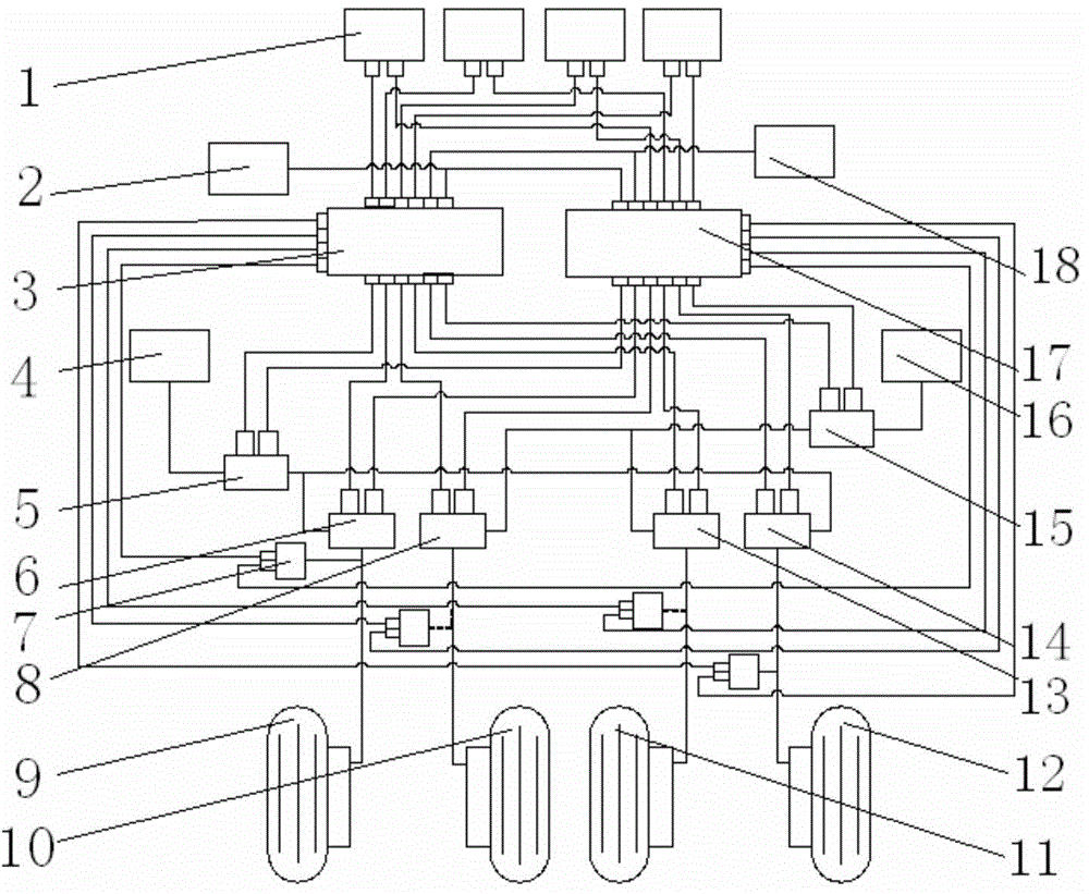
[0021] This embodiment is a brake control system for a certain four-wheeled aircraft.

[0022] The aircraft braking control system proposed in this embodiment is divided into an electrical part and a hydraulic part. Including 4 double-redundant brake command sensors 1, 2 double-redundant hydraulic cut-off valves, 4 double-redundant pressure servo valves, 4 pressure sensors 7, normal brake control unit 3, backup brake control unit 17 and 4 brakes machine wheel.

[0023] The two dual-redundancy hydraulic cut-off valves are respectively a first double-redundancy hydraulic cut-off valve 5 and a second double-redundancy hydraulic cut-off valve 15 . The four dual-redundancy pressure servo valves are respectively the first dual-redundancy pressure servo valve 6, the second double-redundancy pressure servo valve 8, the third double-redundancy pressure servo valve 13 and the fourth double-redundancy pressure servo valve 14.

[0024] The electrical part of the aircraft brake control ...


PUM


Abstract

A brake control system of a multi-wheel-train brake machine wheel is divided into an electrical part and a hydraulic part, wherein the electrical part of the airplane brake control system comprises a dual-redundancy brake instruction sensor, a pressure sensor, a normal brake control unit, a standby brake control unit, a first dual-redundancy hydraulic cut-off valve, an electromagnet of a second dual-redundancy hydraulic cut-off valve, a moment motor of a dual-redundancy pressure servo valve, and a main channel and a standby channel of the electrical part are formed; the hydraulic part of the airplane brake control system comprises a main valve body of the dual-redundancy hydraulic cut-off valve, a jet valve body of the dual-redundancy pressure servo valve and a brake machine wheel body, and the hydraulic part is divided into an inner side channel and an outer side channel. The electrical part can ensure that a brake system can work normally in the presence of any single-point electrical faults. The hydraulic part can ensure that when any single hydraulic source is lost or loses effect, and the brake system just loses one second of brake capacity at most and still can meet the requirement for braking of an airplane.

Description

technical field [0001] The invention relates to a brake control system for a multi-wheel-system aircraft, in particular to a brake system capable of ensuring the safety of the take-off and landing braking of the multi-wheel-system aircraft under any single point of failure. Background technique [0002] With the development of aviation technology, the take-off weight of large aircraft continues to increase, and the corresponding configuration of its landing gear becomes increasingly complex, and the number of wheels and brake components increases. important factor. [0003] According to Civil Aircraft Airworthiness Regulations CCAR25 Part 25.735b: The brake system and its related systems must be designed and constructed in such a way that they are not damaged by any electrical, pneumatic, hydraulic or mechanical connection components or transmission components or any single hydraulic source or other braking energy source. In the event of a loss, the aircraft can be stopped ...

Claims


Application Information

Patent Timeline
IPC IPC(8): B60T13/66B64C25/44
Inventor 刘劲松张琦范淑芳周宏博王红玲
Owner XIAN AVIATION BRAKE TECH
Learn More