Guiding and clamping device

A technology of clamping device and guide rod, applied in positioning device, clamping, supporting and other directions, can solve the problems of unstable clamping operation and easy damage to the surface of the workpiece, and achieve the effect of stable movement, protection of the workpiece and reduction of impact.

Inactive Publication Date: 2014-08-27
重庆市丰收农机制造有限公司
View PDF0 Cites 1 Cited by
  • Summary
  • Abstract
  • Description
  • Claims
  • Application Information

AI Technical Summary

Problems solved by technology

[0003] The invention provides a guide clamping device to solve the problems existing in the existing cl

Method used


Image

  • Guiding and clamping device

Examples


Example Embodiment

[0008] The present invention will be further described in detail below in conjunction with the drawings and specific embodiments:

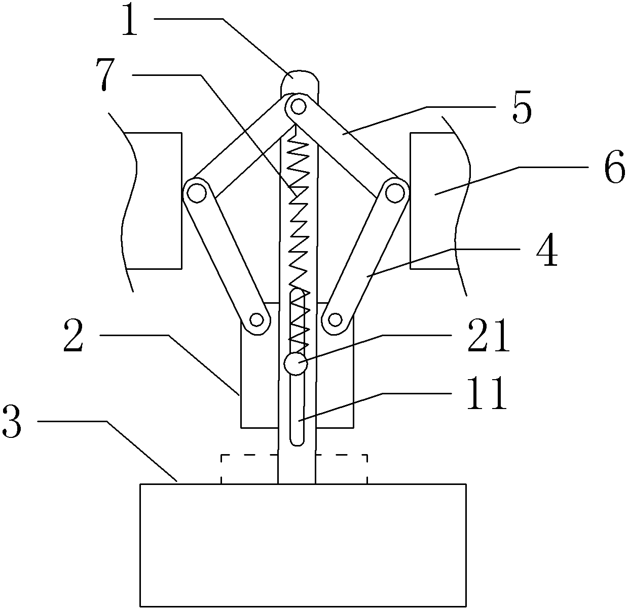
[0009] Such as figure 1 The guide clamping device shown includes a guide rod 1. The guide rod 1 is provided with a long guide groove 11 along the length of the guide rod. A pressure block 2 is provided on the side of the guide rod 1, and a pressure block 2 is provided below the pressure block 2. There is a clamping table 3, a guide pin 21 is provided in the middle of the pressure block 2, and the guide pin 21 is placed in the guide groove 11 and can slide along the guide groove 11. The upper ends of the pressure block 2 are respectively hinged with first driving rods 4, two first The ends of the driving rods are hinged to the second driving rod 5, the ends of the two second driving rods are both hinged to the top of the guide rod 1, and the hinge points of the two first driving rods and the second driving rods are provided with push blocks 6 , The p...


PUM


Abstract

The invention discloses a guiding and clamping device. The guiding and clamping device aims to solve the problems that by the adoption of an existing clamping device, the surface of a workpiece is prone to damage and clamping operation is instable. The guiding and clamping device comprises a guide rod. A long-strip-shaped guide groove is formed in the guide rod in the length direction of the guide rod. A pressing block is arranged on the side of the guide rod. A clamping platform is arranged below the pressing block. A guide pin is arranged in the middle of the pressing block. The guide pin is arranged in the guide groove and can slide along the guide groove. The two ends of the upper portion of the pressing block are respectively hinged to a first drive rod. The ends of the two first drive rods are respectively hinged to a second drive rod. The ends of the two second drive rods are hinged to the top end of the guide rod. Pushing blocks are arranged at the hinged points of the two first drive rods and the hinged points of second drive rods respectively. The total length of each first drive rod and the corresponding second drive rod is larger than the distance between the hinged point at the top end of each second drive rod and the bottom of the guide groove. When the guiding and clamping device are used for clamping a workpiece, the workpiece is not prone to damage, and clamping action is stable.

Description

technical field [0001] The invention relates to a fixture used for machine tool processing, in particular to a guiding and clamping device. Background technique [0002] Clamping devices are widely used in the processing of machine tool parts. At present, in the production and processing of small batches of workpieces, it is generally required that the structure of the clamping device is simple and easy to operate. Therefore, the existing clamping devices generally use cylinders or oil cylinders to directly drive the clamping plate. The clamping device of this structure often has the following problems: 1. There is no indirect transmission mechanism, and the piston rod directly drives the pressure plate to clamp the workpiece, which often has a strong impact on the workpiece at the moment of clamping. Workpieces with special requirements, etc., will cause damage; 2. The operation is unstable during the process of clamping the workpiece, and it is easy to produce slig...

Claims


Application Information

Patent Timeline
IPC IPC(8): B23Q3/00
CPCB23Q3/12
Inventor 陈彪
Owner 重庆市丰收农机制造有限公司
Why Eureka
Try Eureka