
Flexible trabecular bone structure interbody fusion cage

A technology of intervertebral fusion and trabecular bone, applied in the field of intervertebral fusion, can solve the problems of displacement of intervertebral fusion, unsatisfactory long-term curative effect, high recurrence rate, etc., and achieve the effect of avoiding the loss of mobility

Active Publication Date: 2014-08-27
武汉光谷北宸医疗器械有限公司
View PDF12 Cites 14 Cited by
  • Summary
  • Abstract
  • Description
  • Claims
  • Application Information

AI Technical Summary

Problems solved by technology

However, the recurrence rate of simple herniated disc nucleus pulposus is high, and the reduction of intervertebral load leads to the increase of facet joint load, which can easily lead to osteoarthritis, and the long-term effect is not satisfactory (Jin Anmin, Yao Weitao, Zhang Hui. The curative effect of lumbar disc herniation is not The cause analysis and countermeasures of the best. Chinese Journal of Orthopedics, 2003, 23(11): 657-660.); Although the intervertebral bone fusion through bone grafting or intervertebral fusion is satisfactory for the short-term curative effect of intervertebral discogenic diseases, there are Non-fusion of some intervertebral bone grafts, displacement and subsidence of intervertebral cages, accelerated degeneration of intervertebral discs in adjacent segments, and stiffness of fixed segments, the long-term efficacy is not satisfactory; artificial disc replacement still has problems The range of motion of the intervertebral disc segment, but the surgical trauma, difficulty, high cost, occasional serious adverse reactions, etc. have certain limitations in use

Method used


Image

  • Flexible trabecular bone structure interbody fusion cage

Examples


Embodiment Construction

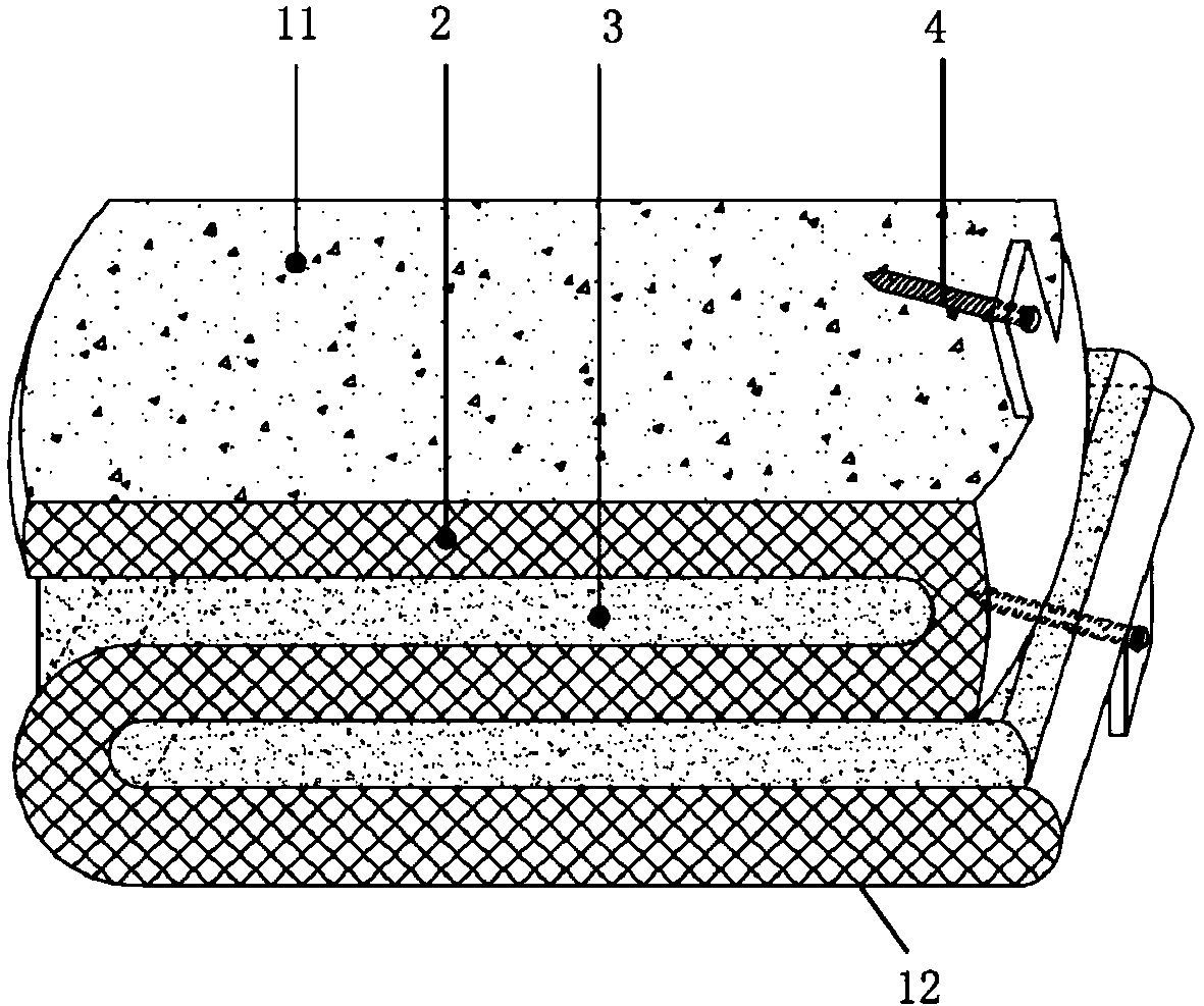
[0020] Such as figure 1 As shown, the embodiment of the present invention is provided with a leaf spring framework 2, an upper trabecular structure layer 11 is provided on the upper surface of the leaf spring framework 2, and a lower trabecular structure layer 12 is provided on the lower surface of the leaf spring framework 2, The polycarbonate polyurethane elastomer 3 is filled in the gap of the leaf spring skeleton 2, and screw holes are arranged on the front or rear edge of the upper trabecular bone structure layer 11 and the lower bone trabecular structure layer 12, and the screw holes are used for passing through Locking screws 4 fix the present invention on the upper and lower vertebral bodies of the fusion segment.

[0021] The upper surface of the upper trabecular bone structure layer 11 can be sprayed with hydroxyapatite coating, and the lower surface of the lower trabecular bone structure layer 12 can be sprayed with lower hydroxyapatite coating.

[0022] Both the u...


PUM


Abstract

The invention discloses a flexible trabecular bone structure interbody fusion cage, and relates to an interbody fusion cage capable of substituting intervertebral disk functions. The flexible trabecular bone structure interbody fusion cage can fuse an upper vertebral body with a lower vertebral body, and can reserve the normal gap between the fused vertebral bodies and the mobility balance between the fused vertebral bodies. The fusion cage is provided with a plate spring skeleton, the upper surface of the plate spring skeleton is provided with an upper trabecular bone structure layer, the lower surface of the plate spring skeleton is provided with a lower trabecular bone structure layer, a polycarbonate polyurethane elastomer is added to the gaps of the plate spring skeleton, the front edge or the rear edge of each of the upper trabecular bone structure layer and the lower trabecular bone structure layer is provided with a screw, and the screw is used for fixing the fusion cage on the upper and lower vertebral bodies through locking bolts. The flexible trabecular bone structure interbody fusion cage can be used for the operation treatment of cervical vertebra and lumbar discogenic diseases, and reserves the functions of the intervertebral disc as possible while fusing the adjacent vertebral bodies in order to avoid the disappear of the mobility balance between the fused vertebral bodies.

Description

technical field [0001] The invention relates to an intervertebral fusion device that can replace the function of the intervertebral disc, in particular to a flexible bone trabecular that can preserve the normal gap and balance of motion between the fused vertebral bodies while fusing with the upper and lower vertebral bodies Structural Intervertebral Fusion Cage. Background technique [0002] The intervertebral disc is both tough and elastic. When it is under pressure, it is compressed, and after the pressure is removed, it recovers. It acts like an "elastic cushion", which can buffer the shock of the external force on the spine and increase the range of motion of the spine. As the degenerative changes of the intervertebral disc become more and more serious, the compression of the spinal nerves caused by the source of the intervertebral disc is also the main cause of clinical neck, shoulder, low back and leg pain. Existing treatment methods for intervertebral discs include ...

Claims


Application Information

Patent Timeline
IPC IPC(8): A61F2/44A61B17/70
CPCA61F2/44A61F2002/30001
Inventor 张衣北
Owner 武汉光谷北宸医疗器械有限公司
Learn More