Construction element

A technology of structural components and components, applied in the field of structural components, can solve problems such as high cost and complicated subsequent replacement, and achieve the effect of stable position and space saving

Active Publication Date: 2014-08-20
约亨拉克
View PDF7 Cites 2 Cited by
  • Summary
  • Abstract
  • Description
  • Claims
  • Application Information

AI Technical Summary

Problems solved by technology

Thus, however, subsequent replacement in the event of loss of vacuum and checking the function of the insulating effe

Method used


Image

  • Construction element
  • Construction element
  • Construction element

Examples


Embodiment Construction

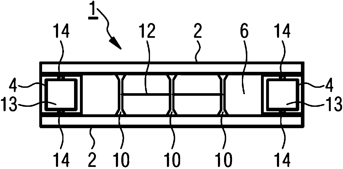
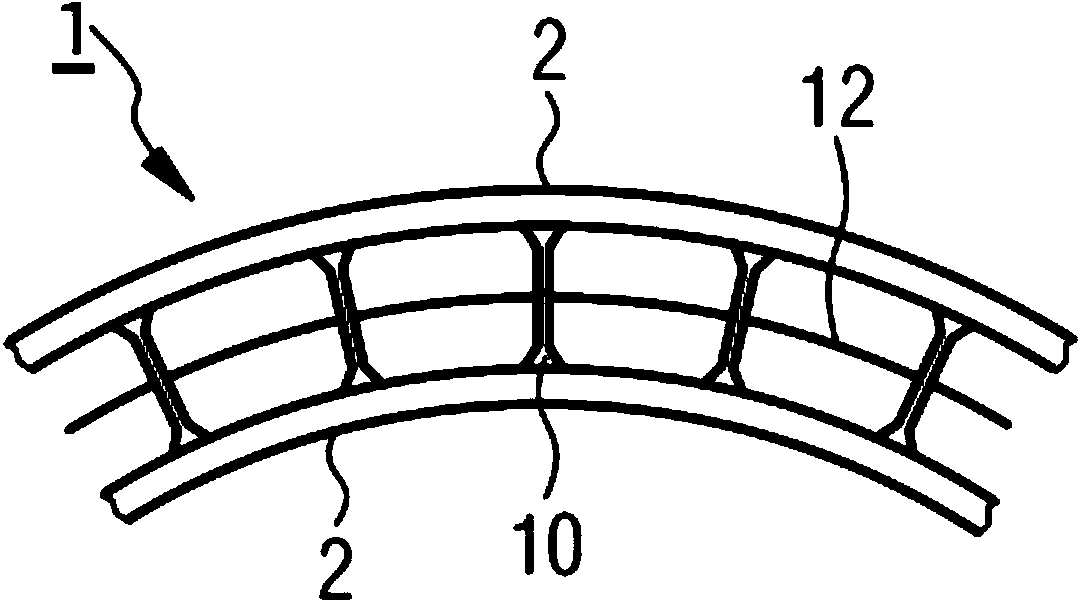
[0099] figure 1 A cross-sectional view through the structural element 1 is shown. The structural element 1 comprises: a cover layer 2 , which is configured as a fixed plate and arranged parallel to each other; and a frame structure 4 forming an edge, closed along the periphery and thus forming a cavity 6 . Since the frame structure 4 is integrally formed with the cover layer 2, the cavity can be sealed in a gas-tight manner. Furthermore, a spacer element 10 is arranged in the cavity 6, said spacer element being configured as a cylinder thickened at its ends. The spacer elements 10 are arranged perpendicular to the cover layers 2 and stabilize the spacing of the cover layers 2 relative to each other.

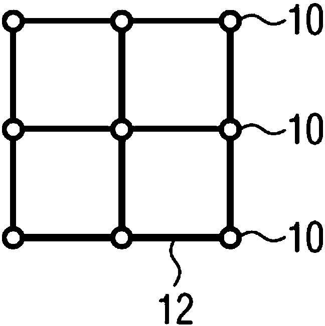
[0100]During assembly, the cover layer 2, the frame structure 4 and the spacer elements 10 are supplied separately. The covering layer 2 and the frame structure 4 can thus be transported in a space-saving manner. The spacer elements 10 are interconnected by a grid structure 1...


PUM


Abstract

Using the lowest possible amount of resources, a system is to be provided with a structural element (1), which system allows the characteristics of a vacuum to be used in the construction sector in a particularly simple manner. In particular, with a substantial freedom from thermal bridges, it is possible to also subsequently insulate a building envelope, for example, in situ at the lowest possible cost and this insulation is to be flexibly adaptable to changes of the building envelope. For this purpose, the structural element (1) comprises two cover layers (2) arranged substantially parallel to one another and a closed frame structure (4) which is formed integrally with the cover layers (2) and is arranged between said cover layers (2) such that a gastight cavity (6) is formed, said cavity (6) containing a vacuum.

Description

technical field [0001] The present invention relates to a structural element comprising: two cover layers arranged substantially parallel to each other; and a closed frame structure integrally formed with the cover layers and arranged between the cover layers such that An airtight cavity is formed that contains a vacuum. The invention also relates to a method for producing such a structural element and to a building and a method for equipping said building. Such structural elements and methods are known, for example, from WO 2006 / 003199 A1. Background technique [0002] One of the most important challenges for the future is to drastically reduce the consumption of raw materials. In the construction sector in particular, a great deal of potential remains untapped for future projects as well as for existing projects. This concerns not only the energy consumed by use, but also the grey energy associated with the construction, maintenance and demolition of buildings. Another...

Claims


Application Information

Patent Timeline
IPC IPC(8): B64B1/14E04B1/80
CPCB64B1/14E04H15/20E04B2/30E04B1/803E04B2/40B64C3/00Y10T29/49616Y02A30/242Y02B80/10E06B3/66304E06B3/6775E06B3/677E06B3/6612E06B3/6715
Inventor 斯蒂芬·拉克
Owner 约亨拉克
Why Eureka
Try Eureka