Drill bit and method of manufacturing machined object using same

A technology of drill bits and cutting parts, which is applied in the direction of manufacturing tools, metal processing equipment, drilling/drilling equipment, etc., which can solve the problems of material deterioration, deterioration, and drill breakage, etc., and achieve excellent breakage resistance, inhibition Effects of deflection and excellent hole machinability

Active Publication Date: 2016-08-24
KYOCERA CORP
View PDF5 Cites 0 Cited by
  • Summary
  • Abstract
  • Description
  • Claims
  • Application Information

AI Technical Summary

Problems solved by technology

[0003] However, in the case of drills in which flutes merge as described above, chips generated from each cutting edge tend to clog easily at the position where the two flutes merge.
In addition, due to the heat generated at the joining point due to clogged chips, the material to be cut may be deteriorated and the inner wall of the machining hole may be deformed (deterioration of surface roughness)
In addition, when the chip is blocked at the confluence position of the groove, the stress (cutting torque) applied to the position increases during machining, which may cause the drill to break
In addition, at the confluence position of the grooves, the shape of the grooves changes due to the influence of the grooves on each other, so the flow of chips passing through each groove changes, which may damage the inner wall of the machining hole

Method used


Image

  • Drill bit and method of manufacturing machined object using same
  • Drill bit and method of manufacturing machined object using same
  • Drill bit and method of manufacturing machined object using same

Examples


no. 1 approach

[0021] Below, refer to Figure 1 ~ Figure 4 , the first embodiment of the drill according to the present invention will be described in detail.

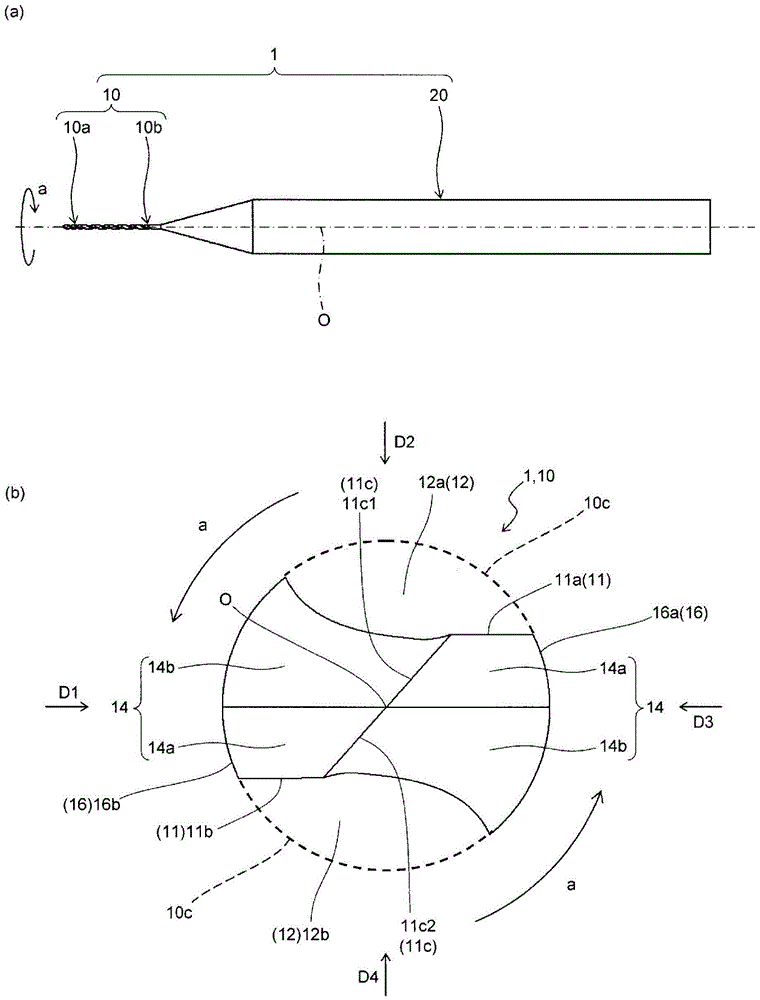
[0022] Such as figure 1 As shown in (a), the drill 1 according to this embodiment generally includes a main body (base end) 20 held by a rotating spindle of a machine tool, etc., and a cutting part 10 provided on one end side of the main body 20 . The main body portion 20 is a portion designed according to the shape of the rotating shaft of the machine tool. The cutting portion 10 is a portion in contact with the workpiece. It should be noted, figure 1 Arrow a in (a) indicates the rotation direction of the drill 1 .

[0023] The cutting portion 10 is a portion that plays a major role in cutting the workpiece. If specified, such as figure 1 (b) and figure 2 As shown in (a), the cutting part 10 of this embodiment has two cutting edges 11 (first cutting edge 11a and second cutting edge 11b ) provided at a distance from each othe...

no. 2 approach

[0050] Next, refer to Figure 5 , the drill bit according to the second embodiment of the present invention will be described in detail. It should be noted that, in Figure 5 , sometimes against the above Figure 1 ~ Figure 4 The same components are given the same reference numerals and their descriptions are omitted. It should be noted that, for the drill bit of this embodiment, figure 1 The basic structure of the drill bit 1 is the same as that of the drill bit 1 of the first embodiment, so the differences from the drill bit 1 of the first embodiment will be mainly described, and descriptions of overlapping contents will be omitted.

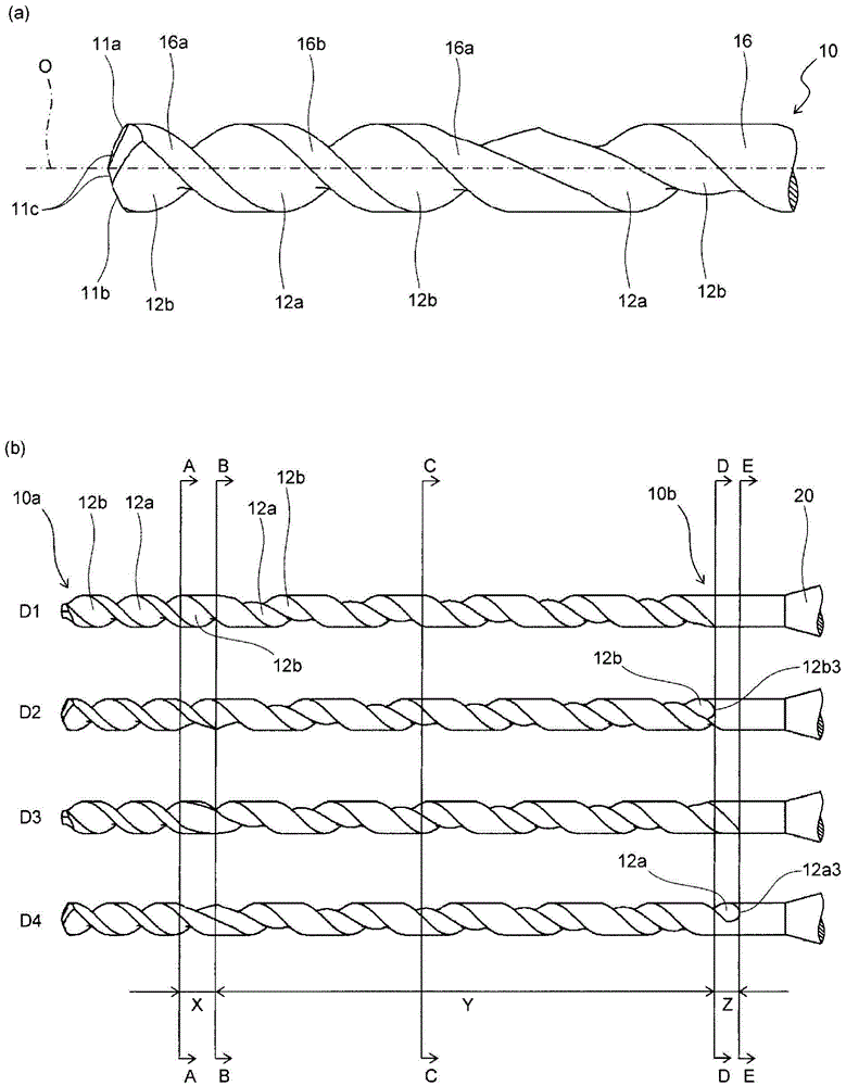
[0051] In this embodiment, different from the above-mentioned embodiments, as Figure 5 As shown, in the partial confluence region Y, the first groove 12a is located closer to the front end 10a side than the second groove 12b, and in the terminal region Z, only the rear end 12a3 of the first groove 12a and the second groove exist. 12b3 in ...

no. 3 approach

[0054] Next, refer to Figure 6 and Figure 7 A drill according to a third embodiment of the present invention will be described in detail. It should be noted that, in Figure 6 and Figure 7 , sometimes against the above Figure 1 to Figure 5 The same components are given the same reference numerals and their descriptions are omitted. For the drill bit of this embodiment, due to figure 1 The basic structure of the drill bit 1 is the same as that of the drill bit 1 of the first embodiment, so the differences from the drill bit 1 of the first embodiment will be mainly described, and descriptions of overlapping contents will be omitted.

[0055] In this embodiment, different from the above-mentioned embodiments, as Figure 6As shown, in the partial confluence region Y, the first groove 12a is located closer to the rear end 10b side than the second groove 12b, and in the terminal region Z, only the rear end 12a3 of the first groove 12a and the second groove 12a exist. The ...


PUM


Abstract

The drill of an embodiment of the present invention is provided with a solid cylindrical-shaped cutting section having: a first cutting edge and a second cutting edge, which are provided at the front end of the cutting section so as to be separated from each other; and a first groove and a second groove, which respectively continue to the first cutting edge and the second cutting edge and which helically extend toward the rear end of the cutting section. The cutting section has: an independent region in which the first groove and the second groove are located so as to be separated from each other and which is configured so that, in a side view, the first groove and the second groove approach each other toward the rear end; a partial joint region which continues to the rear end side of the independent region and in which the first groove and the second groove extend parallel to each other while a part of the first groove and a part of the second groove join with each other; and an end region which continues to the rear end side of the partial joint region and in which only one of the rear end of the first groove and the rear end of the second groove is present. A method for manufacturing a drilled product using the drill is provided.

Description

technical field [0001] The present invention relates to a drill and a method for manufacturing a machined object using the drill. Background technique [0002] Japanese Patent Application Laid-Open No. 2007-307642 discloses a technical solution as follows: in a drill with two blades and two twisted grooves connected to each blade at the front end of the main body, the two twisted grooves recede from the front end of the main body. Merge at the specified amount of position to form a trough. [0003] However, in a drill in which flutes merge as described above, chips generated from each cutting edge tend to clog easily at the position where the two flutes merge. Furthermore, since the confluent position is heated due to clogged chips, the quality of the workpiece may be deteriorated and the inner wall of the machined hole may be deformed (deterioration of the surface roughness). In addition, when chips are jammed at the confluence position of the groove, the stress (cutting ...

Claims


Application Information

Patent Timeline
Patent Type & Authority Patents(China)
IPC IPC(8): B23B51/00
CPCB23B41/14B23B51/02B23B2251/406
Inventor 小川浩
Owner KYOCERA CORP
Why Eureka
Try Eureka