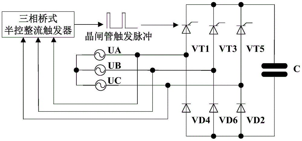
A three-phase bridge half-controlled rectifier trigger circuit with protection function
A three-phase bridge type, semi-controlled rectification technology, applied in emergency protection circuit devices, output power conversion devices, AC power input conversion to DC power output and other directions, can solve the problem of large starting current, contact oxidation, device impact, etc. problems, to ensure safe and reliable work, flexible control methods, and small current impact.
- Summary
- Abstract
- Description
- Claims
- Application Information
AI Technical Summary
Problems solved by technology
Method used
Image

Examples
Embodiment Construction
[0030] The present invention will be further explained below in conjunction with the accompanying drawings.
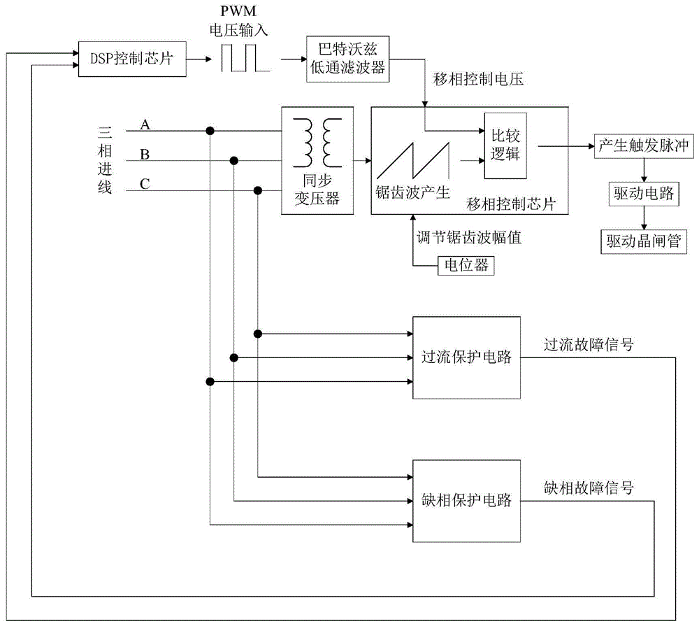
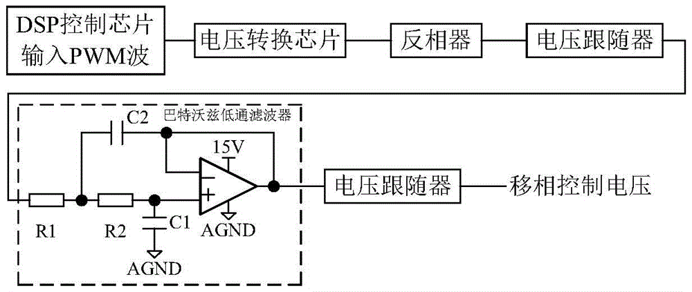
[0031] like figure 2 As shown, a three-phase bridge-type semi-controlled rectification trigger circuit with a protection function includes a phase-shift control voltage generating circuit, a phase-shift trigger pulse generating circuit and a driving circuit. like image 3 As shown, the phase-shift control voltage generating circuit includes a DSP control chip, a voltage conversion chip, an inverter, a voltage follower and a Butterworth low-pass filter. The DSP control chip outputs a PWM voltage with a duty ratio of 10% to 90%. After the PWM voltage is linearly transformed by the voltage conversion chip, it is converted into a PWM voltage with an average value of 1.5V to 13.5V and then input to the inverter for voltage inversion. phase to obtain a PWM voltage with an average value of 13.5V~1.5V; the inverted PWM voltage is input to the Butterworth low-pass filter thr...
PUM
 Abstract
Description
Claims
Application Information
 - R&D
- Intellectual Property
- Life Sciences
- Materials
- Tech Scout
- Unparalleled Data Quality
- Higher Quality Content
- 60% Fewer Hallucinations
Browse by: Latest US Patents, China's latest patents, Technical Efficacy Thesaurus, Application Domain, Technology Topic, Popular Technical Reports.
© 2025 PatSnap. All rights reserved.Legal|Privacy policy|Modern Slavery Act Transparency Statement|Sitemap|About US| Contact US: help@patsnap.com