
Novel integration house structure

An integrated house and new technology, applied in building components, building structures, walls, etc., can solve the problems of inability to disassemble and assemble at will, labor-intensive, high transportation costs, and achieve good building energy-saving effect, good thermal insulation performance, and mechanical structure. Good results

Active Publication Date: 2014-08-13
湖南千盟园林工程有限公司
View PDF5 Cites 15 Cited by
  • Summary
  • Abstract
  • Description
  • Claims
  • Application Information

AI Technical Summary

Problems solved by technology

[0003] Prefabricated houses are usually produced in factories using standardized production, and its main components can be realized by on-site assembly. However, this type of house has the following disadvantages: (1) The color steel plate wall and the combination method of the wall are not beautiful; (2) It is only suitable for Low-rise and less demanding buildings; (3) limited service life
[0004] Light-weight integrated houses are usually welded or screwed, and installed on site while being manufactured, which has the following disadvantages: (1) The on-site installation takes a long time and consumes a lot of labor, which increases the cost; (2) Due to the construction materials, Due to various reasons such as the manufacturing process and installation method of the structural parts, the building-integrated house cannot be moved as a whole after the construction is completed, nor can it be disassembled arbitrarily, and it is difficult to reuse or the loss of reuse is too large. This method is neither environmentally friendly nor economical.
(3) Non-professionals do not know how to install, and it is not convenient for long-distance consumers to purchase and use
[0005] The box house can only be transported as a whole, the transportation cost is high, and it is only suitable for the construction of small-area houses

Method used


Image

  • Novel integration house structure
  • Novel integration house structure
  • Novel integration house structure

Examples


Embodiment Construction

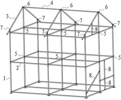
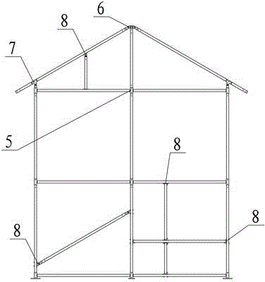
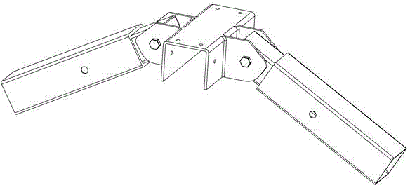
[0029] Depend on Figure 1 to Figure 8 It can be seen that the present invention includes a steel structure frame and a body of wall. The steel structure frame includes vertically connected columns 1 and beams 2, rafters 3 and purlins 4, and the columns 1 and beams 2 are connected and fixed by column and beam connectors 5. The two rafters 3 are connected and fixed by the adjustable purlin connector 6, the column 1 and the rafter 3 are connected and fixed by the adjustable eaves connector 7, and the steel frame structure is supported and reinforced by the support and reinforcement connector 8.

[0030] The post-beam connector 5 of the present invention is composed of an equilateral square column and at least one convex portion welded on the side of the equilateral square column and perpendicular to the extending direction of the equilateral square column.

[0031] The adjustable purlin connector 6 of the present invention is composed of eaves connecting square steel and a base ...


PUM


Abstract

The invention relates to a novel integration house structure. The novel integration house structure comprises a steel structure frame and a wall body and is characterized in that the steel structure frame comprises upright posts and cross beams which are mutually and vertically connected, rafters and purlines, wherein the upright posts and the cross beams adopt upright post and cross beam connecting pieces for connection and fixation; the two rafters are connected and fixed by adjustable purlin connecting pieces; the upright posts and the purlines are connected and fixed by adjustable eave connecting pieces; the steel frame structure is supported and reinforced by supporting and reinforcing connecting pieces. According to the novel integration house structure, the used steel amount is reduced, components are minimized, and the cost is low; industrialized production is realized, the assembly is rapid, and the transportation is convenient; no building garbage and building dust is generated, and the environment is not destroyed; the thermal insulation performance of a roof and the wall body is good, the building energy-saving effect is good, the mechanical structure is good, and the anti-seismic property is good.

Description

technical field [0001] The invention relates to a novel integrated room structure. Background technique [0002] Common building integrated houses used in the market mainly refer to prefabricated houses, light-weight integrated houses (including light steel structure integrated houses and wooden structure integrated houses), box-type houses, which can be used for temporary residence and office of construction personnel. storage space for storage of equipment and materials, temporary housing for earthquake relief, and temporary housing for holding various events. At present, due to various reasons such as building materials, structural parts manufacturing technology, and installation methods, the integrated building cannot be moved as a whole after the construction is completed. If it is not needed, it can only be dismantled as a whole. This method is neither environmentally friendly nor economical. . In the existing technology, the integrated house also has the following l...

Claims


Application Information

Patent Timeline
IPC IPC(8): E04B1/24E04B1/58E04B2/00
Inventor 刘子叔
Owner 湖南千盟园林工程有限公司
Learn More