
Steel anchor beam without corbels

A steel anchor beam and corbel technology, which is applied in bridges, bridge parts, bridge forms, etc., can solve the problems of small vertical cable distance, limited application scope, limited height of cable tower anchorage and space, etc. force ratio, increase the scope of application, and reduce the effect of steel consumption

Active Publication Date: 2014-08-13
CHINA CONSTR THIRD ENG BUREAU GRP CO LTD +1
View PDF4 Cites 4 Cited by
  • Summary
  • Abstract
  • Description
  • Claims
  • Application Information

AI Technical Summary

Problems solved by technology

However, in the anchorage structure of the steel anchor beam, due to the high combined height of the steel anchor beam and the corbel, for the cable-stayed bridge with dense cable system, the vertical cable distance on the bridge tower is small, and the anchorage height and space of the cable tower are limited. Therefore, the scope of application of the traditional steel anchor beam anchorage form is greatly limited

Method used


Image

  • Steel anchor beam without corbels
  • Steel anchor beam without corbels
  • Steel anchor beam without corbels

Examples


Embodiment Construction

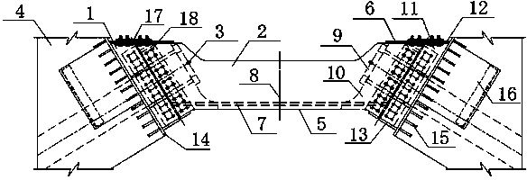
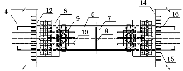
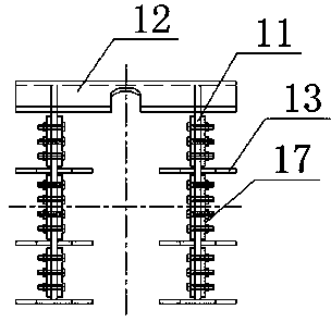
[0025] The present invention will be further explained below in conjunction with the drawings: Figure 1-3 As shown, a corbel-less steel anchor beam includes an end support 1, a middle balance beam 2, and an anchor head 3 of a stay cable. The end support 1 is composed of the support web 11, the support top plate 12, the stiffening plate 13, the wall plate 14 and its shear key. The end support 1 is connected to the concrete tower through the shear stud 15 or PBL shear key 16 on the wall plate 14 The wall 4 is connected. The middle balance beam 2 is an open box section, which is welded by steel plates such as webs 5, top plates 6, bottom plates 7, and transverse partitions 8 on both sides. The supporting web 11 and the supporting top plate 12 of the end support 1 are respectively connected with the web 5 and the top plate 6 of the middle balance beam 2 by a connecting plate 17 and high-strength bolts. The bolt holes on the supporting web 11 of the end support 1 and the web 5 of...


PUM


Abstract

The invention provides a steel anchor beam without corbels. The steel anchor beam without the corbels comprises end supports (1), a middle balance beam (2) and stay cable anchoring heads (3). The end supports (1) are connected with tower walls (4) through shear studs (15) or PBL shear keys (16), and the end supports (1) are connected with a web (5) and top plates (6) of the middle balance beam (2) through high-strength bolts. The stay cable anchoring heads (3) are symmetrically arranged on a bottom plate (7) located on the inner sides of the two ends of the web (5) of the middle balance beam (2), and under-anchor #-shaped plates (10) of the stay cable anchoring heads (3) are connected with the web (5), the top plates (6) and the bottom plate (7) of the middle balance beam (2). The steel anchor beam without the corbels has the advantages that the overall height of the steel anchor beam structure is reduced; when a stay cable is tensioned, the middle balance beam slides on connecting bolt hole positions in a self-adaptive mode in the cable force direction, constraint in the horizontal direction of the middle balance beam is released, so that deformation is generated, and the middle balance beam bears the horizontal component balance part of the stay cable. According to the steel anchor beam without the corbels, it is guaranteed that the steel anchor beam bears the most horizontal component of the stay cable, the problem of height limit of the steel anchor beam is solved, meanwhile steel consumption is reduced, and therefore the application range of the steel anchor beam is widened.

Description

technical field [0001] The invention relates to the technical field of design and manufacture of bridge components, in particular to a steel anchor beam connected to the end of a cable-stayed cable tower of a cable-stayed bridge. [0002] Background technique [0003] The anchorage area of ​​cable-stayed bridge tower is an important structure for force transmission between the cable-stayed cable and the main tower. Its local stress is large and the force transmission is complicated, which has a great influence on the durability of the bridge tower. There are three main types of anchorage structures for cable towers of long-span cable-stayed bridges: steel anchor boxes, steel anchor beams, and hoop prestress. The steel anchor box is actually an anchoring scheme for a steel-concrete composite structure. The concrete tower wall and the steel anchor box are jointly stressed during the dead load stage. Generally, a certain horizontal circumferential prestress needs to be set to ...

Claims


Application Information

Patent Timeline
IPC IPC(8): E01D19/14E01D11/04
Inventor 戴小松周强新刘强李劲秦建刚毛晓龙何承林
Owner CHINA CONSTR THIRD ENG BUREAU GRP CO LTD
Learn More