
LED (Light-Emitting Diode) radiating fin splicing method and equipment

A heat sink and equipment technology, applied in welding equipment, heat exchange equipment, non-electric welding equipment, etc., can solve the problem that the welding method cannot meet the requirements

Inactive Publication Date: 2014-08-13
东莞市闻誉实业有限公司
View PDF7 Cites 0 Cited by
  • Summary
  • Abstract
  • Description
  • Claims
  • Application Information

AI Technical Summary

Problems solved by technology

Since the LED heat sink needs to be assembled with the LED, the splicing accuracy of the LED heat sink is very high, such as the regularity of the splicing interface and the flatness of the splicing surface. The traditional welding method cannot meet the requirements.

Method used


Image

  • LED (Light-Emitting Diode) radiating fin splicing method and equipment
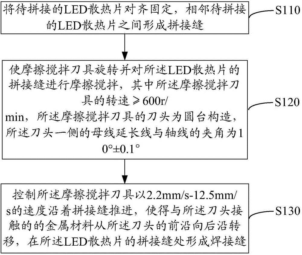
  • LED (Light-Emitting Diode) radiating fin splicing method and equipment
  • LED (Light-Emitting Diode) radiating fin splicing method and equipment

Examples


Embodiment Construction

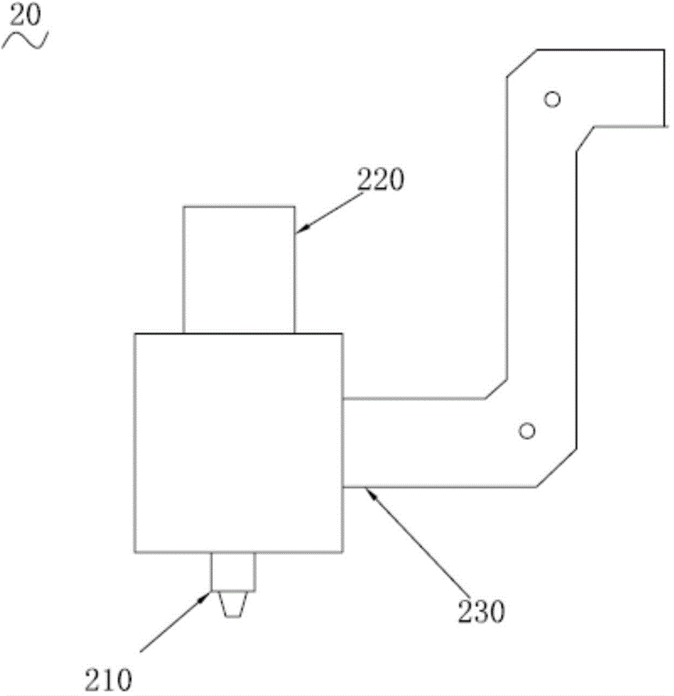
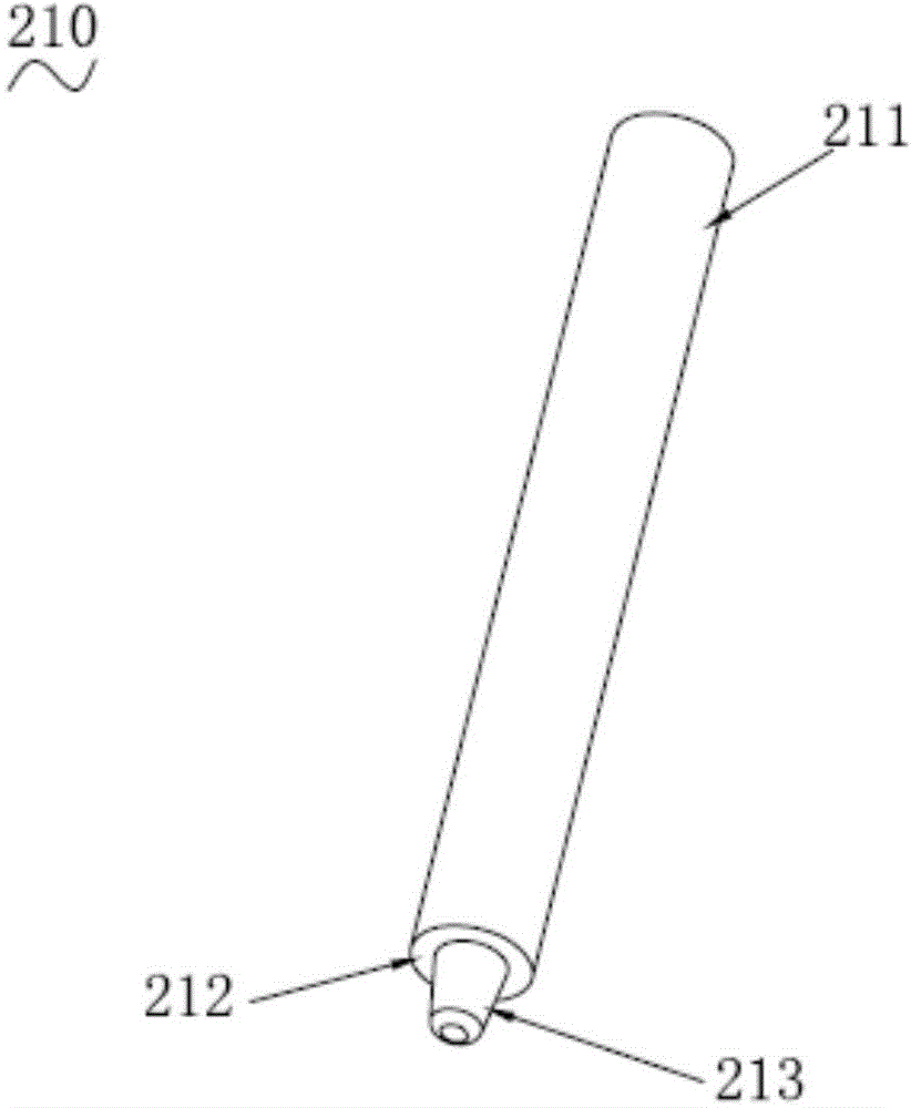
[0021] In order to further understand the features, technical means, specific objectives and functions achieved by the present invention, and to analyze the advantages and spirit of the present invention, a further understanding of the present invention can be obtained through the following detailed description of the present invention in conjunction with the accompanying drawings and specific embodiments.

[0022] See attached figure 1 , which is a schematic flowchart of a method for splicing LED heat sinks according to an embodiment of the present invention.

[0023] The LED heat sink splicing method includes steps:

[0024] Step S110: align and fix the LED heat sinks to be spliced, and form splicing seams between adjacent LED heat sinks to be spliced.

[0025] Since there will be external force on the LED heat sink during the welding process, it is necessary to fix the LED heat sink to avoid displacement during the welding process. The LED heat sink exerts pressure.

[0...


PUM


Abstract

The invention discloses an LED (Light-Emitting Diode) radiating fin splicing method. The method comprises the following steps: aligning and fixing LED radiating fins to be spliced, wherein splicing seams are formed among adjacent LED radiating fins to be spliced; driving a friction stirring tool to rotate, and abrading and stirring the splicing seams of the LED radiating fins; controlling the friction stirring tool to advance along the splicing seams in order to transfer metal materials contacted with a tool bit from the front edge to the rear edge of the tool bit; forming welding seams on the splicing seams of the LED radiating fins. Meanwhile, the invention further provides LED radiating fin splicing equipment. High temperature is generated by the friction of the friction stirring tool rotating at a high speed with the metal materials of the splicing seams of the LED radiating fins for melting the metal materials, stirring is performed to mix the metal materials on the splicing seams, and solidified welding seams are formed after cooling, so that the LED radiating fins are spliced together. The splicing width and depth of the LED radiating fins can be controlled by adopting the friction stirring tool, so that splicing of the splicing interfaces as well as the flatness of splicing planes of the LED radiating fins can be controlled accurately, and the splicing accuracy is high.

Description

technical field [0001] The invention relates to the field of splicing heat sinks, in particular to a splicing method and equipment for LED heat sinks. Background technique [0002] High-power LEDs will dissipate a lot of heat during operation, so a heat sink is installed to promote heat dissipation to avoid high temperature burning out the LEDs. With the emergence of large LEDs, the corresponding LED heat sinks are also becoming larger and larger. The general LED heat sink is formed by die casting, and the cost of making the mold is very high. If it is necessary to make large-scale LED heat sinks, it is very expensive to directly produce large-scale molds. Therefore, general manufacturers will solve the problem by splicing multiple LED heat sinks into one large LED heat sink by splicing. Since the LED heat sink needs to be assembled with the LED, the splicing accuracy of the LED heat sink is very high, such as the regularity of the splicing interface and the flatness of t...

Claims


Application Information

Patent Timeline
IPC IPC(8): B23K20/12B23K101/14
CPCB23K20/122B23K20/1255
Inventor 叶伟炳
Owner 东莞市闻誉实业有限公司
Learn More