
Ripple wave suppressor circuit of program-controlled direct-current power supply

A ripple suppressor and DC power supply technology, applied in electrical components, output power conversion devices, etc., can solve the problem that the power loss cannot be further reduced, the power consumption of the post-stage voltage regulator circuit is large, and the front and rear stages cannot achieve synchronous tracking adjustment. and other problems, to achieve good application value, efficient load point adjustment, and improve the effect of dynamic response performance

Active Publication Date: 2014-08-06
CHINA ELECTRONIS TECH INSTR CO LTD
View PDF5 Cites 10 Cited by
  • Summary
  • Abstract
  • Description
  • Claims
  • Application Information

AI Technical Summary

Problems solved by technology

However, in order to obtain good fast response performance, the post-stage voltage regulator circuit must ensure a certain input and output pressure difference
At the same time, when the program-controlled output voltage changes, the front and rear stages cannot achieve good synchronous tracking and adjustment. Therefore, the front stage often uses a fixed voltage output, resulting in a large power consumption of the rear stage voltage regulator circuit at low voltage output, which cannot further reduce the power supply. loss

Method used


Image

  • Ripple wave suppressor circuit of program-controlled direct-current power supply
  • Ripple wave suppressor circuit of program-controlled direct-current power supply
  • Ripple wave suppressor circuit of program-controlled direct-current power supply

Examples


specific Embodiment

[0028] The present invention requires that the program-controlled voltage output is 0-20V, and the maximum output current is 10A. Since the output range of the circuit DAC is -5V-0V, the values ​​of the resistors R1, R2, R5 and R6 are related to the output voltage Vo and the working range of the operational amplifier N1 Regarding, because the power supply voltage of the operational amplifier is 12V, in order to ensure good adjustment characteristics, the maximum value of Vmon is determined to be 10V, so k1 is taken as 0.5, k2 is taken as 0.5, and the resistance value R1 is selected as 20k, R2 as 10k, and R5 as 10k. R6 is 10k, and the accuracy is 0.1%. metal film resistors. The operational amplifier N1 adopts high-precision dual operational amplifier LT1013, which can complete the precise adjustment of the active voltage; the adjustment tube V1 adopts HUF75345P, with a typical on-resistance of 7mΩ, which can reduce the voltage drop of 10A to within 200mV, effectively improving ...


PUM


Abstract

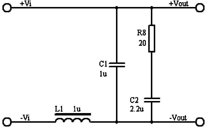
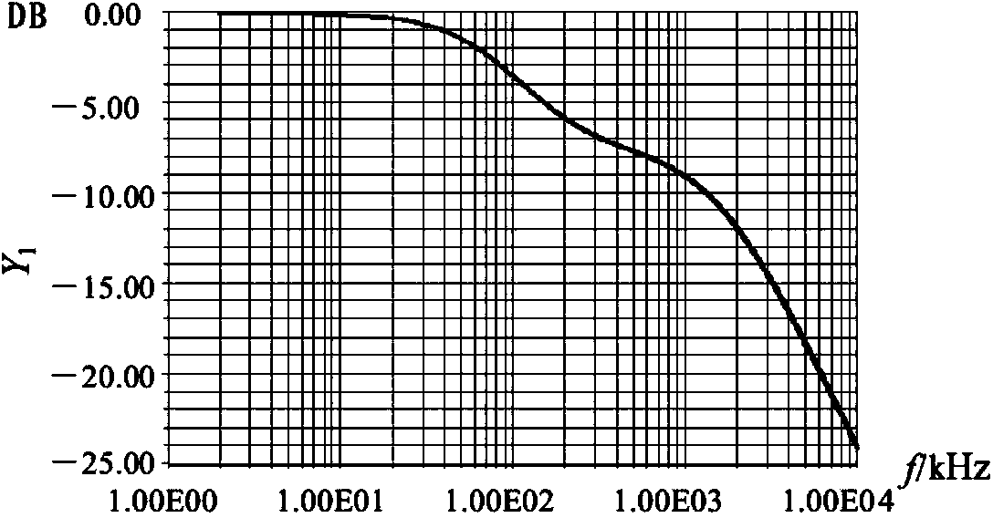
The invention discloses a ripple wave suppressor circuit of a program-controlled direct-current power supply. According to the ripple wave suppressor circuit of the program-controlled direct-current power supply, an active low-pass filter and a passive filter are connected between a positive output line of the direct-current power supply and a negative output line of the direct-current power supply after a capacitor C3 is connected between the positive output line of the direct-current power supply and the negative output line of the direct-current power supply, the active low-pass filter comprises an N-channel high-power MOSFET V1, a front-stage operational amplifier N1:1 with a dynamic compensation function and a rear-stage operational amplifier N1:2 with a dynamic compensation function, and the passive filter comprises an inductor L1 and a capacitor C1. According to the ripple wave suppressor circuit of the program-controlled direct-current power supply, high-frequency and low-frequency ripple wave noise output by the power supply can be lowered, the dynamic response performance can be improved, and the output precision and the stability are improved. The front-stage and rear-stage synchronous tracking control is adopted, accurate adjustment enabling the voltage difference to be low can be achieved, and the conversion efficiency of the power supply is effectively improved. As a result, the ripple wave suppressor circuit of the program-controlled direct-current power supply has high application value in the aspect of design of high-precision program-controlled power supplies.

Description

technical field [0001] The invention relates to the field of program-controlled power supplies, in particular to a ripple suppressor circuit for a program-controlled DC power supply. Background technique [0002] Programmable DC power supply is an essential equipment in automatic test system. In the process of national modernization, various automatic test systems have emerged as the times require, directly serving civil fields such as scientific research and production, and the demand for program-controlled DC power systems is also increasing. In various automatic test systems, such as base station test systems and electronic equipment system-level automatic test platforms, high-precision, low-noise programmable power supplies are required, and the voltage is required to be programmable. Programmable DC power supply is an ideal device to provide bias power and incentives to components or final products in an automatic test environment, and is an essential test instrument f...

Claims


Application Information

Patent Timeline
IPC IPC(8): H02M1/14
Inventor 李彬汪定华王文廷王俊张根苗王群敖翔郭宇飞
Owner CHINA ELECTRONIS TECH INSTR CO LTD
Learn More