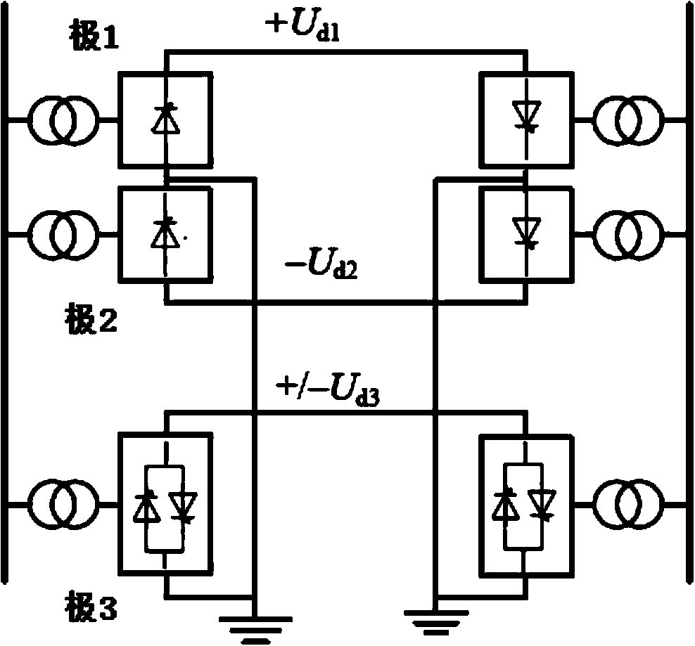
Compact modularized multi-level tripolar direct-current power transmission system
A modular multi-level, DC power transmission system technology, applied in the direction of AC power input conversion to DC power output, power transmission AC network, electrical components, etc., to achieve good engineering application value, small footprint, and low overall transformation cost Effect
- Summary
- Abstract
- Description
- Claims
- Application Information
AI Technical Summary
Problems solved by technology
Method used
Image
Examples
Embodiment 1
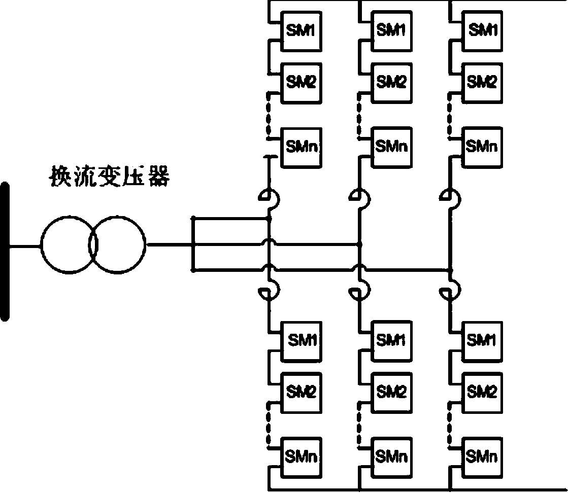
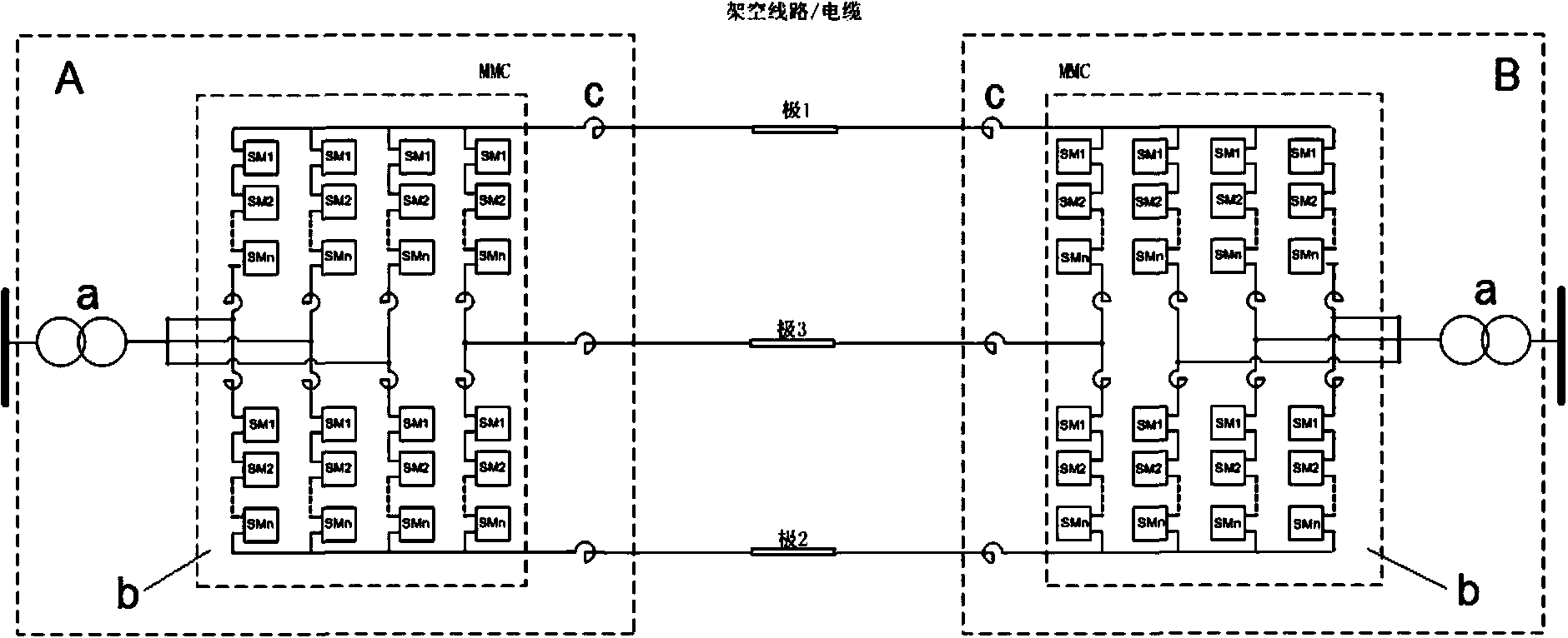
[0031] figure 2 Shown is a typical three-phase six-arm MMC structure diagram, in figure 2 On the basis of the MMC structure, one phase bridge arm is added to form a four-phase eight-arm converter, and a four-phase eight-arm converter is installed in the rectifier station and the inverter station respectively to connect with three DC lines to realize three-pole Direct current transmission, the specific scheme is as follows:
[0032] Such as image 3 As shown, a compact modular multi-level three-pole DC power transmission system realizes three-pole DC power transmission, including rectification side subsystem A, DC line and inverter side subsystem B connected in sequence, and the DC line includes three wires , are pole 1 DC line, pole 2 DC line and pole 3 DC line respectively; the rectification side subsystem A and the inverter side subsystem B both include a converter transformer a and a converter b, and the converter b is four Eight-phase modular multilevel converter (MMC...
Embodiment 2
[0037] The difference between this embodiment and Embodiment 1 is that the DC line is an overhead line. Since the overhead line has a high probability of temporary faults, if the fault is cleared by tripping the AC side switch, the power outage time will be longer, affecting the availability of the entire system. Therefore, the fault on the DC side needs to be cleared through the control of the converter itself. For this reason, the sub-module of the modular multilevel rectifier adopts a clamping double sub-module structure, including two clamping sub-modules. The specific structure of the clamp sub-module is as follows Figure 5 As shown, each clamping twin sub-module is composed of the first equivalent half-bridge unit and the second equivalent half-bridge unit connected in series and parallel through the clamping diodes D6, D7 and the guiding IGBT (T5) with the anti-parallel diode D5; the first The collector of the first IGBT (TI) is connected to one end of the first capaci...
PUM
 Abstract
Description
Claims
Application Information
 - R&D Engineer
- R&D Manager
- IP Professional
- Industry Leading Data Capabilities
- Powerful AI technology
- Patent DNA Extraction
Browse by: Latest US Patents, China's latest patents, Technical Efficacy Thesaurus, Application Domain, Technology Topic, Popular Technical Reports.
© 2024 PatSnap. All rights reserved.Legal|Privacy policy|Modern Slavery Act Transparency Statement|Sitemap|About US| Contact US: help@patsnap.com


