
Multi-angle remote sensing automatic observation system based on unmanned aerial vehicle

An automatic observation and multi-angle technology, applied in the direction of attitude control, etc., can solve the problems of inconvenient observation, high cost, and inflexible flight in remote areas, so as to reduce redundant analysis time, prevent collision accidents with mountains, and ensure imaging resolution Effect

Inactive Publication Date: 2014-08-06
BEIJING NORMAL UNIVERSITY
View PDF5 Cites 4 Cited by
  • Summary
  • Abstract
  • Description
  • Claims
  • Application Information

AI Technical Summary

Problems solved by technology

From the point of view of the existing aviation multi-angle observation data acquisition methods, the observation is mainly carried out by fixed-wing aircraft equipped with sensors. The problems faced by this observation method are huge cost, inflexible flight routes, long flight time, and cumbersome procedures. All the data obtained in this way is relatively small
[0003] At present, the development of the aviation multi-angle automatic observation system needs to solve the following problems: first, the problem of fast data acquisition, the previous aerial telemetry platform is not flexible in flight, and the flight time is long, during which the sun's altitude angle will change significantly , resulting in inaccurate observation data, especially for thermal infrared observations
The second is the issue of flexibility, including both time and space. Traditional aerial observations use large fixed-wing aircraft, which require special airstrips, which is very inconvenient for observations in remote areas. small remote mountains

Method used


Image

  • Multi-angle remote sensing automatic observation system based on unmanned aerial vehicle
  • Multi-angle remote sensing automatic observation system based on unmanned aerial vehicle
  • Multi-angle remote sensing automatic observation system based on unmanned aerial vehicle

Examples


Embodiment Construction

[0028] The present invention will be further described below with reference to the accompanying drawings and specific embodiments.

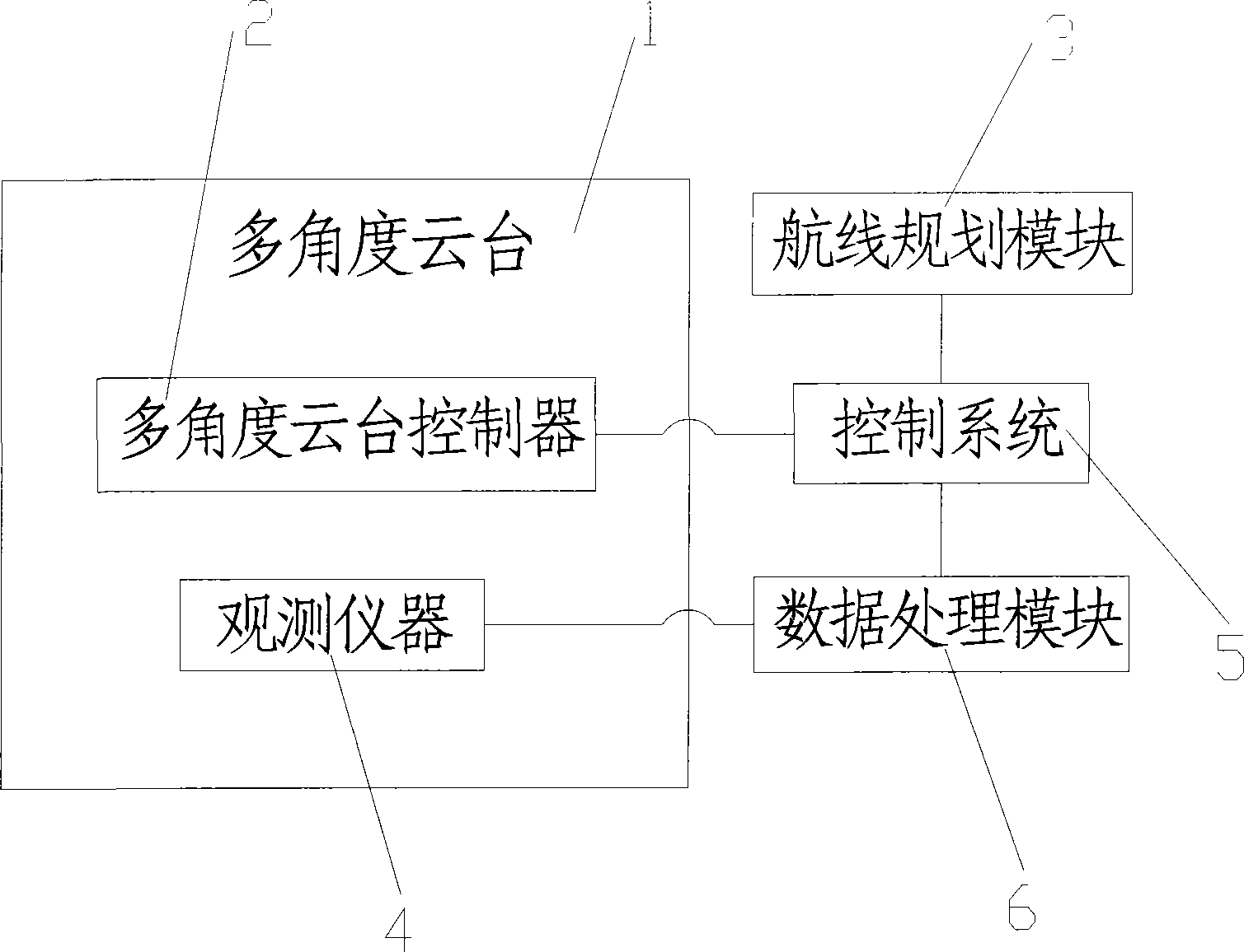
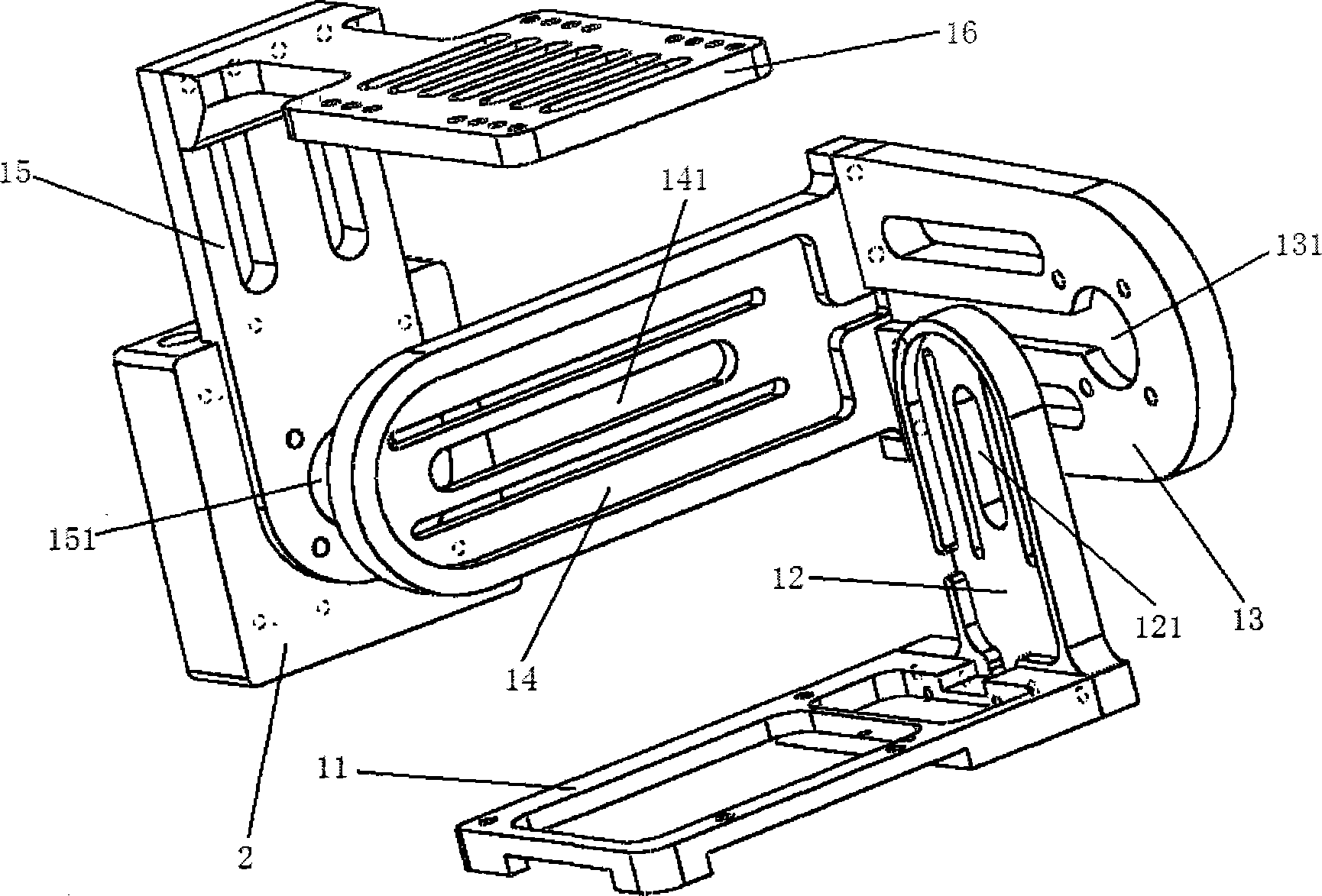
[0029] Such as Figure 1 to Figure 10Shown: a kind of multi-angle remote sensing automatic observation system based on unmanned aerial vehicle of the embodiment of the present invention, comprises multi-angle pan-tilt 1, multi-angle pan-tilt controller 2, route planning module 3, data processing module 6 and control system 5 , the multi-angle pan-tilt 1 is fixedly installed on the drone, the multi-angle pan-tilt controller 2 is arranged on the multi-angle pan-tilt 1, the multi-angle pan-tilt controller 2 and the control system 5 Communication connection, the multi-angle cloud platform 1 is provided with an observation instrument 4, and the route planning module 3 is connected to the control system 5, through which the route planning module 3 can automatically plan a reasonable flight route for the observation task, and can Complete observation t...


PUM


Abstract

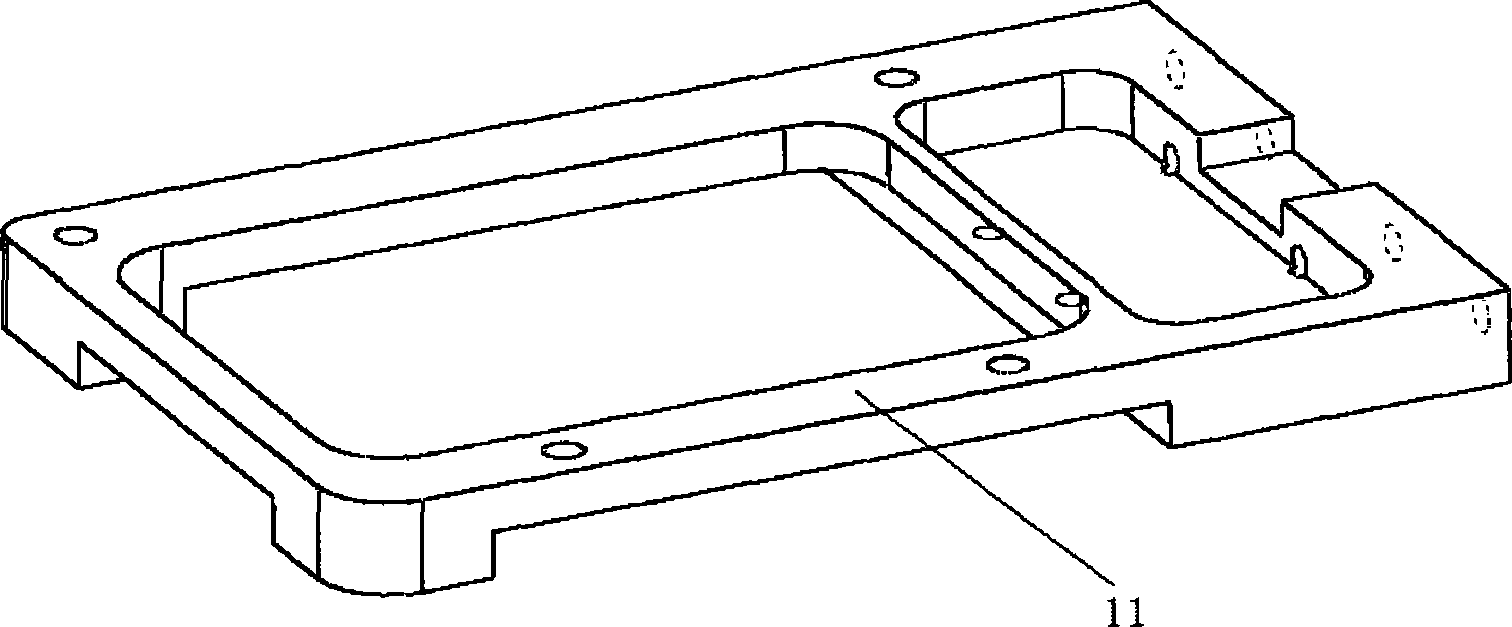
The invention relates to a multi-angle remote sensing automatic observation system based on an unmanned aerial vehicle. The multi-angle remote sensing automatic observation system comprises a multi-angle cradle head, a multi-angle cradle head controller, an air line planning module, a data processing module and a control system. The multi-angle cradle head is fixedly installed on the unmanned aerial vehicle. The multi-angle cradle head controller is arranged on the multi-angle cradle head and in communication connection with the control system. An observation instrument is arranged on the multi-angle cradle head. The air line planning module is connected with the control system. The data processing module is connected with the observation instrument and the control system. The multi-angle cradle head comprises a pitching plate, a pitching vertical plate, a transverse rolling plate, a transverse rolling vertical plate, a cloud platform support and a cloud platform. The multi-angle remote sensing automatic observation system based on the unmanned aerial vehicle is convenient to carry, capable of conducting automatic observation and high in observation efficiency and adaptability.

Description

technical field [0001] The invention relates to an unmanned aerial vehicle-based multi-angle remote sensing automatic observation system. Background technique [0002] In recent years, with the rapid development of quantitative remote sensing, multi-angle remote sensing has become one of the hot research fields, but the acquisition of multi-angle data is a difficult problem, so the development of various multi-angle observation systems is the basic work of multi-angle remote sensing . From the perspective of multi-angle remote sensing data acquisition methods, there are currently three main methods: based on satellite platforms, based on aerial platforms, and based on ground observations. The satellite platform can provide a large amount of multi-angle observation data on the ground through the superposition of the sensor field of view, and the data is stable and reliable. Not applicable in remote sensing. Therefore, various scientific research units have invented a serie...

Claims


Application Information

Patent Timeline
IPC IPC(8): G05D1/08
Inventor 穆西晗闫凯漆建波阎广建刘鹏
Owner BEIJING NORMAL UNIVERSITY
Learn More