Flat plate type argon blowing joint

A flat type, joint body technology, applied in the direction of pipes/pipe joints/fittings, flange connections, passing components, etc., can solve the problems of excessively high tolerances for joint positioning, easy collisions, inconvenient use, etc., and achieve allowable deviations Low requirements, guaranteed sealing effect, and less exposed parts

Inactive Publication Date: 2014-08-06
上海坤冶工程技术有限公司
View PDF5 Cites 23 Cited by
  • Summary
  • Abstract
  • Description
  • Claims
  • Application Information

AI Technical Summary

Problems solved by technology

[0003] At present, most of the argon blowing joints used in the ladle bottom argon blowing process have complex structures and a certain height; when in use, due to various objective reasons such as large ladle mass, large inertia, and errors in lifting operations, etc. If the positioning is not accurate, it will be offset during use. The offset of the position will cause the joint to receive a lateral compensation force during use, and the long-term force will make the joint easy to damage; There are many exposed parts, which are prone to collision and damage; when working, the allowable deviation of docking positioning is too high, the operation is difficult, and it is inconvenient to use

Method used


Image

  • Flat plate type argon blowing joint
  • Flat plate type argon blowing joint
  • Flat plate type argon blowing joint

Examples


Embodiment

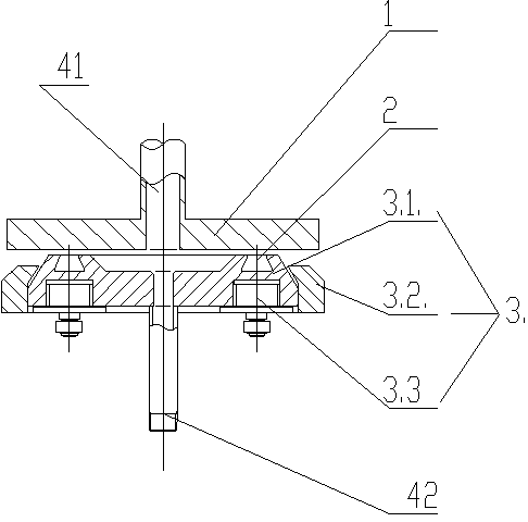
[0020] As shown in the figure, a flat type argon blowing joint is characterized in that it consists of an upper part 1 of the argon blowing joint, a sealing ring 2, a lower part 3 of the argon blowing joint, and connecting pipes 41 and 42; the upper part 1 of the argon blowing joint is fixedly installed on On the ladle, it is connected to the argon blowing element through the connecting pipe 41.

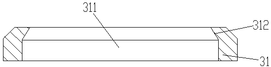
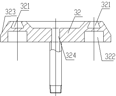
[0021] As shown in the figure, the lower part 3 of the argon blowing joint includes a fixing seat 31 , a joint body 32 and a pressing force adjustment assembly 33 . The outside of the fixed seat 31 is square, and the interior of the fixed seat 31 is provided with a circular concave hole 311, and the joint body 32 is placed in the circular concave hole 311, and the top of the joint body 32 is provided with an annular groove 321. The section of the groove 321 is trapezoidal, and the sealing ring 2 is installed in the annular groove 321. The sealing ring 2 is located at the connection b...


PUM


Abstract

The invention discloses a flat plate type argon blowing joint which comprises an upper argon blowing joint portion, a sealing ring, a lower argon blowing joint portion and a connecting pipe. The lower argon blowing joint portion comprises a fixed base, a joint body and pressing force adjusting assemblies. The joint body is installed in the fixed base. The sealing ring is installed at the top end of the joint body. The bottom face of the fixed base is provided with a plurality of pressing force adjusting assemblies. Each pressing force adjusting assembly comprises an elastic compensation part and a fixing plate. The fixing plates are located on the bottoms of the elastic compensation parts. The elastic compensation parts are supported on steel ladle supports under the bottom face of the fixed base through the fixing plates. The structure is improved, the number of the assembled parts is small, and installation is easy to carry out; the number of exposed parts is small, collision and damage are not prone to occurring, and the cost is lowered; the requirement for butt-joint locating allowable deviation is low, and use is convenient; the argon blowing joint can not be influenced by splashing of steel slag and molten steel easily.

Description

technical field [0001] The invention relates to a flat argon blowing joint, which belongs to the technical field of steelmaking. Background technique [0002] Ladle bottom blowing argon craftsman is a very important link in the steelmaking process. Bottom blowing of the ladle blows argon into the molten steel, disperses in the molten steel in the form of bubbles and floats up. The surrounding molten steel is driven by buoyancy, so that the molten steel flows in the ladle, thereby accelerating the melting of alloys and solvents added to the molten steel, promoting the uniform composition and temperature of the steel and the floating of inclusions, and removing the non-metallic in the steel Inclusions and harmful gases to achieve the purpose of refining molten steel. [0003] At present, most of the argon blowing joints used in the ladle bottom argon blowing process have complex structures and a certain height; when in use, due to various objective reasons such as large ladl...

Claims


Application Information

Patent Timeline
Patent Type & Authority Applications(China)
IPC IPC(8): F16L23/032F16L23/18
CPCC21C7/072
Inventor 许瑞华
Owner 上海坤冶工程技术有限公司
Why Eureka
Try Eureka