
Vehicle bumper with buffer energy storage function

A technology for bumpers and vehicles, applied in the field of vehicle bumpers, can solve the problems of material plastic deformation buffer structure damage, crush box structure damage, limited energy absorption capacity, etc., and achieves the effect of improving energy buffering effect and protecting driving safety.

Inactive Publication Date: 2014-08-06
广西农垦昌菱农场有限公司
View PDF9 Cites 8 Cited by
  • Summary
  • Abstract
  • Description
  • Claims
  • Application Information

AI Technical Summary

Problems solved by technology

In this invention, the crush box mainly relies on the deformation of materials and structures to absorb energy, and its ability to absorb energy is limited, and it is easy to cause damage to the structure of the crush box after multiple absorption collisions
[0004] Existing bumpers mainly absorb the energy generated by the collision through the deformation of functional materials and special buffers. The energy absorption capacity is limited, and it is easy to cause the plastic deformation of the material or the damage of the buffer structure to fail when the impact is large. These performances Defects directly endanger the safety of passengers and vehicles

Method used


Image

  • Vehicle bumper with buffer energy storage function
  • Vehicle bumper with buffer energy storage function
  • Vehicle bumper with buffer energy storage function

Examples


Embodiment

[0038] In order to make the purpose, technical solution and advantages of the present invention more clear, the present invention will be further described in detail below in conjunction with the accompanying drawings and embodiments. It should be understood that the specific embodiments described here are only used to explain the present invention, not to limit the present invention.

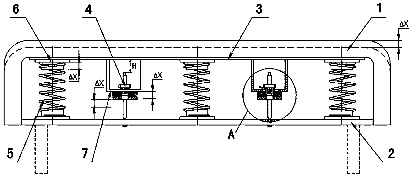
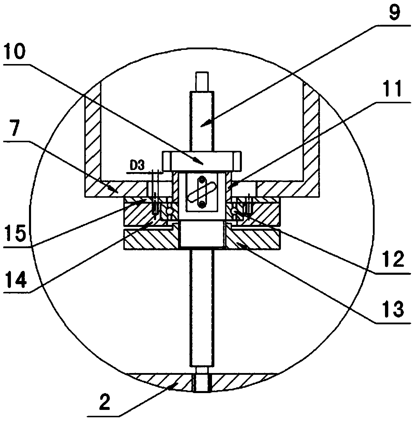
[0039] Such as figure 1 , 2 As shown, a vehicle bumper with buffer energy storage function includes a beam 2 connected to the vehicle and an outer fixed plate 3, and two buffer energy stores are arranged side by side between the beam 2 and the outer fixed plate 3 device 4 and three buffer springs 5, the buffer accumulator 4 includes a ball screw 9, a screw nut 10, a sleeve 11, a bearing 12, a flywheel 13, a bearing holder 14 and a bearing cover 15, wherein One end of the ball screw 9 is threadedly connected with the beam 2, and the other end is screwed with the screw nut 10, and the outer cir...


PUM


Abstract

The invention discloses a vehicle bumper with a buffer energy storage function. The vehicle bumper with the buffer energy storage function comprises a cross beam connected with a vehicle and an outer fixing plate. At least one buffer energy accumulator and at least two buffer springs are arranged between the cross beam and the outer fixing plate side by side in a spaced mode. Each buffer energy accumulator comprises a ball screw, a screw nut, a sleeve, a bearing, a flywheel, a bearing fixing base and a bearing block cover plate, wherein one end of the ball screw is connected with the cross beam, and the screw nut is arranged at the other end of the ball screw in a rotating mode; the sleeve, the bearing and the flywheel are arranged on the outer circle of the screw nut in sequence from top to bottom in a sleeved mode, and the flywheel is arranged on the outer circle of the screw nut in a rotating mode; the outer circle of the bearing is sleeved with the bearing fixing base and the bearing block cover plate which are connected with each other; the sleeve is rotatably arranged in a mounting hole in a penetrating mode, and the mounting hole is formed in the bottom of a U-shaped mounting base arranged on the outer fixing plate; the bearing fixing base and the bearing block cover plate are connected with the U-shaped mounting base. According to the vehicle bumper with the buffer energy storage function, energy is absorbed through a mechanical device, and the vehicle bumper is convenient to install, longer in service life and capable of quickly restoring under the elasticity of the buffer springs after multiple times of collision.

Description

technical field [0001] The invention relates to a vehicle bumper, in particular to a vehicle bumper with a buffer energy storage function, which belongs to the technical field of automobiles. Background technique [0002] The application number is 201310202223.1, and the invention patent application titled "A Bumper Buffer for Automobiles" discloses a low-cost vehicle bumper buffer, which can be used to replace the bumper buffer made of EPP foam and reduce production costs. Process requirements and costs. The technical scheme is to make the vehicle bumper buffer into a grid shape on the side facing the bumper body. This structure will reduce the overall density and strength, and it can collapse with the bumper body for a certain distance in the event of a collision, playing a certain role in buffering and absorbing energy. However, the reduction in the stiffness of the bumper in this invention will easily cause the bumper to deform greatly during a collision, resulting in ...

Claims


Application Information

Patent Timeline
Patent Type & Authority Applications(China)
IPC IPC(8): B60R19/18
Inventor 温华兵昝浩杨兴林陈宁桑晶晶刘林波
Owner 广西农垦昌菱农场有限公司
Learn More