
B ultrasonic image-based space-time quantization monitoring system and method for realizing ultrasonic cavitation during HIFU (High Intensity Focused Ultrasound) treatment

A technology of image realization and image acquisition system, which is applied in the field of spatiotemporal quantification monitoring system, can solve the problems of cavitation bubble group positioning and inaccurate quantification, and achieve the effects of precise quantification, increased complexity and high measurement accuracy

Inactive Publication Date: 2014-08-06
NANJING UNIV
View PDF1 Cites 12 Cited by
  • Summary
  • Abstract
  • Description
  • Claims
  • Application Information

AI Technical Summary

Problems solved by technology

[0006] The purpose of the present invention is to overcome the problem of inaccurate positioning and quantification of cavitation bubbles caused by the asynchrony between the HIFU pulse and the monitoring equipment in the existing method for monitoring the cavitation phenomenon of high-intensity focused ultrasound (HIFU), and provides An accurate and easy-to-implement spatiotemporal quantitative monitoring method for acoustic cavitation in high-intensity focused ultrasound (HIFU) therapy based on B-ultrasound images

Method used


Image

  • B ultrasonic image-based space-time quantization monitoring system and method for realizing ultrasonic cavitation during HIFU (High Intensity Focused Ultrasound) treatment
  • B ultrasonic image-based space-time quantization monitoring system and method for realizing ultrasonic cavitation during HIFU (High Intensity Focused Ultrasound) treatment
  • B ultrasonic image-based space-time quantization monitoring system and method for realizing ultrasonic cavitation during HIFU (High Intensity Focused Ultrasound) treatment

Examples


Embodiment 1

[0035] In conjunction with the accompanying drawings, a kind of time-space quantitative monitoring method for realizing acoustic cavitation during HIFU treatment based on B-ultrasound images in this embodiment, the specific steps are as follows:

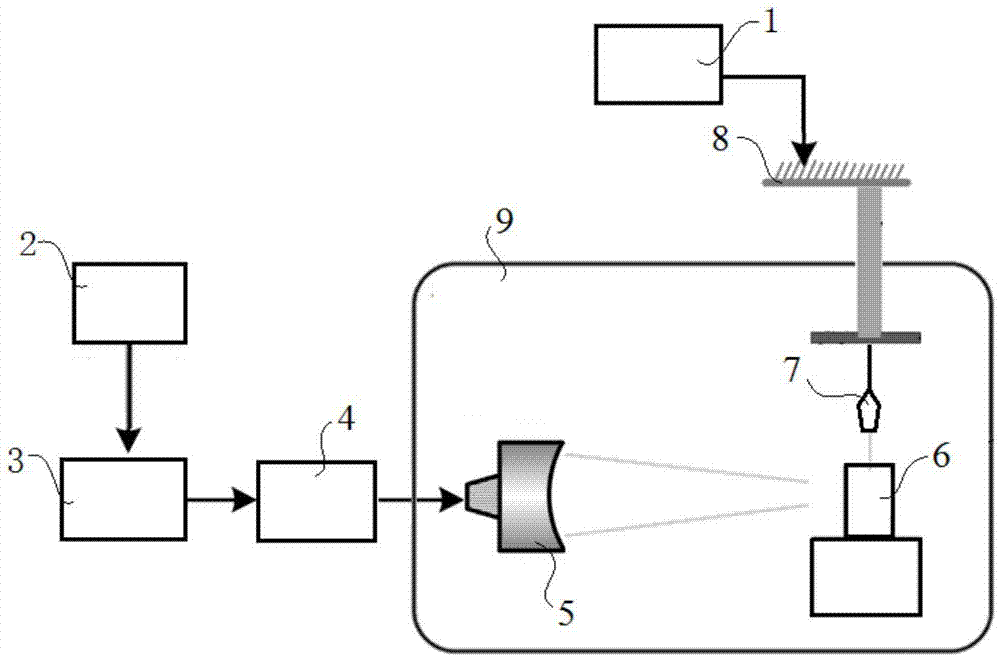
[0036] Step 1. Use the focusing transducer 5 to perform HIFU radiation on the in vitro phantom 6, and use the B-ultrasound image acquisition system 1 to observe and record the spatiotemporal behavior of the cavitation bubble group in the phantom 6. This embodiment implements HIFU treatment based on the B-ultrasound image The time-acoustic space-time quantitative monitoring system such as figure 1 shown.

[0037] In this embodiment, a 1.12 MHz focusing transducer 5 (with a diameter of 10.0 cm and a geometric focal length of 10.0 cm) is used for HIFU irradiation. A 1.12MHz sinusoidal pulse signal was generated by an arbitrary waveform signal generator 2 (Agilent 33250A, USA), and the pulse repetition frequency (PRF) was set to 100Hz. T...


PUM


Abstract

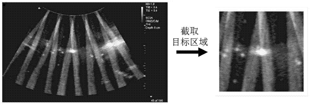
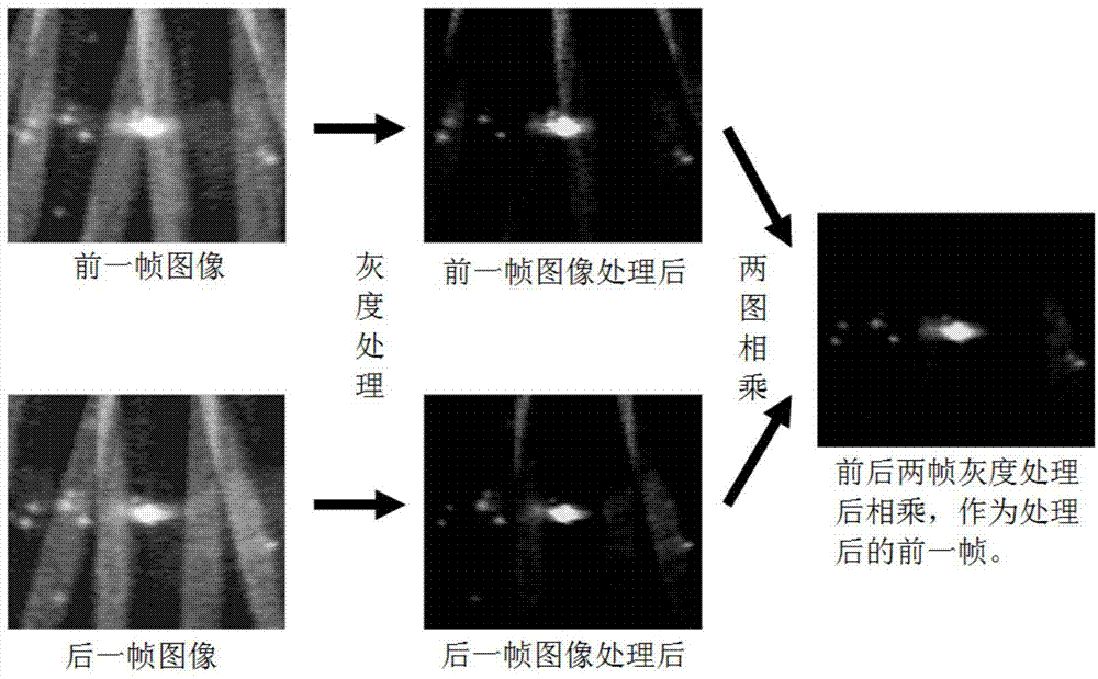
The invention discloses a B ultrasonic image-based space-time quantization monitoring system and a method for realizing ultrasonic cavitation during HIFU (High Intensity Focused Ultrasound) treatment, belonging to the technical field of HIFU sound field measurement. The method comprises the steps of: 1, capturing in-vitro phantom video images; 2, intercepting the region of a cavitation bubble cluster; 3, removing the interference of B ultrasonic image interference fringes; 4, obtaining the region profile of an image cavitation bubble cluster and counting the pixel dots in the region profile; 5, carrying out the operation of step four on each frame of image to obtain the change rule of the area of the cavitation bubble cluster along with the time. The system comprises a B ultrasonic image capturing system, a signal generator, a power amplifier, an impedance matching circuit, a phantom, an ultrasonic probe, a three-dimensional motion platform and a focusing energy converter, and is simple in structure and convenient to control. According to the B ultrasonic image-based space-time quantization monitoring system and method for realizing ultrasonic cavitation during HIFU treatment, the interference fringes caused by the inconsistence of the B ultrasonic scanning frequency and the HIFU pulse frequency is removed, so that the accurate quantization of the area of the cavitation bubble cluster is realized and the system dispenses with the enhancement of the complexity and the sacrifice of the compatibility.

Description

technical field [0001] The invention relates to the technical field of HIFU sound field measurement, and more specifically, to a time-space quantitative monitoring system and method for realizing time-acoustic cavitation in HIFU treatment based on B-ultrasound images. Background technique [0002] High Intensity Focused Ultrasound (HIFU) can precisely focus sound energy in a predetermined treatment area in the patient's body without damaging normal tissues and organs around the area. These characteristics make HIFU widely used in the treatment of tumors, hemostasis and gene / drug transfection. During HIFU therapy, pre-existing vapor in the fluid or tissue, gas voids, or gas drawn out of the solution can lead to cavitation bubbles as the negative acoustic pressure phase portion of the HIFU pulse passes through the fluid or tissue. The researchers pointed out that cavitation can significantly improve the absorption of sound energy in HIFU treatment, leading to rapid rise in lo...

Claims


Application Information

Patent Timeline
IPC IPC(8): A61N7/00
Inventor 屠娟章东陈楚怡于洁王萧峰
Owner NANJING UNIV
Learn More