A grid printing forming machine

A molding machine and grid technology, applied in the direction of electrode carrier/collector, etc., can solve the problems of low automation and high labor intensity, and achieve the effect of improving standardization and efficiency

Active Publication Date: 2016-09-07
ZHEJIANG HAIYUE AUTOMATIC MACHINERY
View PDF4 Cites 0 Cited by
  • Summary
  • Abstract
  • Description
  • Claims
  • Application Information

AI Technical Summary

Problems solved by technology

The existing grid production device includes a template, the template is provided with a grid forming groove, pouring lead liquid into the grid forming groove, the lead liquid is cooled to form a grid, and the grid is manually taken out from the grid forming groove, so the production Low degree of process automation and high labor intensity

Method used


Image

  • A grid printing forming machine
  • A grid printing forming machine
  • A grid printing forming machine

Examples


Embodiment Construction

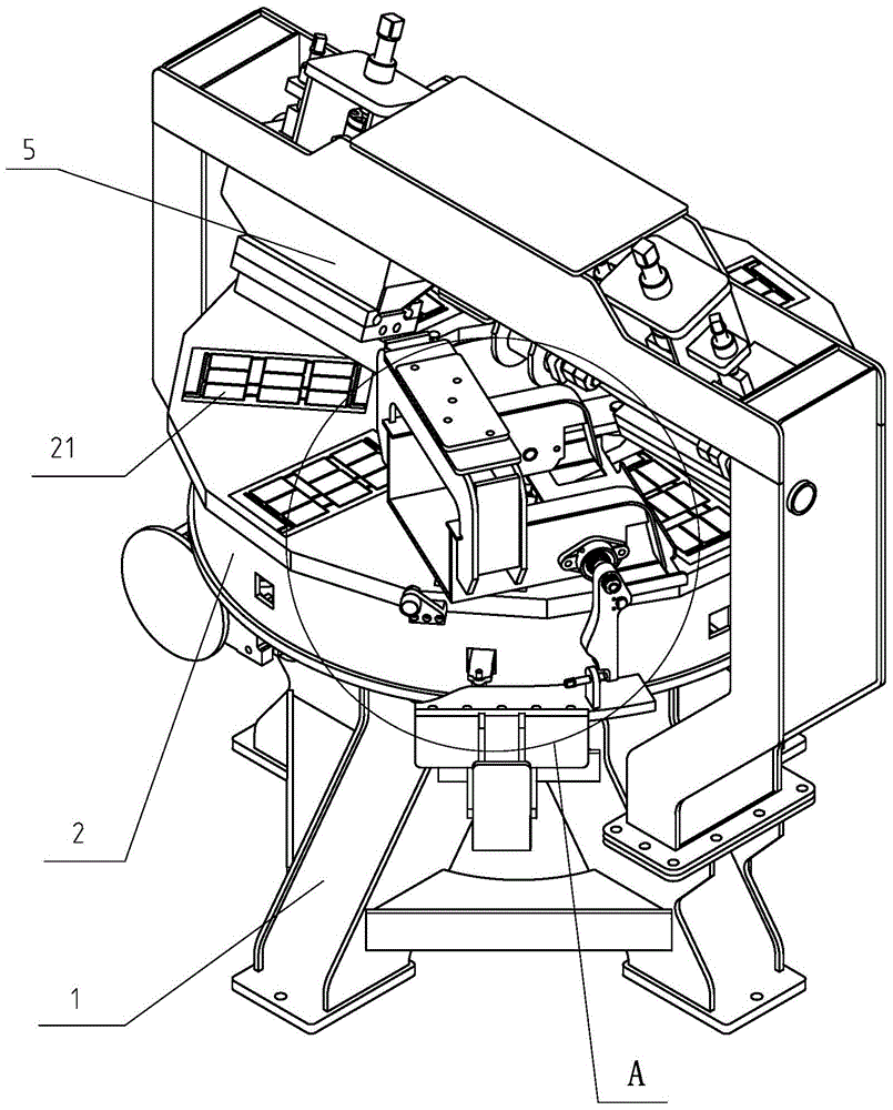
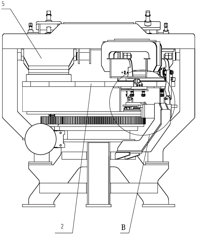
[0025] The invention provides a grid printing forming machine, which includes a frame, on which a turntable and a driving member for driving the turntable are arranged, a plurality of grid forming grooves are arranged at intervals on the turntable, and an ejector device is connected to the bottom of the turntable, along which The rotation direction of the turntable is provided with a printing device and a discharge device in turn. The printing device includes a printing bucket connected to the frame and a brush plate connected to the bottom of the printing bucket. A liquid inlet pipe is connected to the printing bucket, and the bottom surface of the brush plate is a slope , the discharge device includes a left support plate and a right support plate oppositely arranged, and guide rails are provided on the tops of the left support plate and the right support plate, and a curved section that bends downward is provided at the end of the guide rail toward the rotation direction of t...


PUM


Abstract

A grid printing molding machine comprises a frame (1). The frame (1) is provided with a rotating disc (2) and a driving member for driving the rotating disc (2) to rotate. A plurality of grid molding grooves (21) are arranged at intervals on the rotating disc (2). An ejection device is connected below the rotating disc (2). A printing device (5) and a discharging device are orderly arranged along the rotation direction of the rotating disc (2). The printing device (5) comprises a printing hopper (51) connectively mounted on the frame (1) and a brushing plate (52) connected to the bottom of the printing hopper (51). A liquid feeding pipe is connected to the printing hopper (51). The bottom surface of the brushing plate (52) is an inclined surface (512). The discharging device comprises a left support plate (31) and a right support plate (32) arranged oppositely. The tops of the left support plate (31) and the right support plate (32) are both provided with guide rails (33). A bent section (331) bent downwards is arranged on the end of the guide rail (33) facing towards the rotation direction of the rotating disc (2). A rotating plate (34) is rotatably connected between the left support plate (31) and the right support plate (32). A driving device for driving the rotating plate (34) to be turned over so as to move grid tabs along a bent section (331) is connected to the rotating plate (34). The grid printing molding machine is used for solving the problem of low degree of automation during grid production in the prior art and can realize automatic grid production.

Description

【Technical field】 [0001] The invention relates to a storage battery production equipment, especially a grid forming equipment. 【Background technique】 [0002] In a lead-acid battery, the active material of the battery flow reaction needs to be fixed on a grid-like carrier supported by a lead-based alloy. This grid-like carrier is called a grid, and it has two main functions: one is to support the active matter, and the second is to conduct electric current. Therefore, a grid with good conductivity and reasonable structure is very important for the performance of the battery. The existing grid production device includes a template, the template is provided with a grid forming groove, pouring lead liquid into the grid forming groove, the lead liquid is cooled to form a grid, and the grid is manually taken out from the grid forming groove, so the production The process automation is low and the labor intensity is high. 【Content of invention】 [0003] The technical problem ...

Claims


Application Information

Patent Timeline
Patent Type & Authority Patents(China)
IPC IPC(8): H01M4/82
CPCH01M4/82B22D19/00B22D25/04H01M4/73Y02E60/10
Inventor 林雁斌陈义忠周富成王兆华叶治胜雷磊
Owner ZHEJIANG HAIYUE AUTOMATIC MACHINERY
Why Eureka
Try Eureka