Clamping device for magnetic disk

A technology for clamping devices and magnetic disks, which is applied in the fields of recording information storage, instruments, etc., can solve the problems of increasing manufacturing costs, complicated assembly processes, etc., and achieves the effect of firm suspension and prevention of falling off.

Inactive Publication Date: 2005-02-16
ALPS ALPINE CO LTD
View PDF0 Cites 0 Cited by
  • Summary
  • Abstract
  • Description
  • Claims
  • Application Information

AI Technical Summary

Problems solved by technology

[0012] However, in the conventional clamping device, in order to realize the front / outer support of the driving pin, the fixed pin 101b for swinging the clamping arm 105 is adopted, so the number of parts is increased, and it is necessary to set and fix the clamping device when manufacturing this clamping device. Using the corresponding positions of the hole 105c and the hole portion 101a, or performing operations such as piercing and riveting of the fixing pin 101b, not only the assembly process is complicated, but also the manufacturing cost is increased.

Method used


Image

  • Clamping device for magnetic disk
  • Clamping device for magnetic disk
  • Clamping device for magnetic disk

Examples


Embodiment Construction

[0068] Embodiments of the present invention will be described below in conjunction with the accompanying drawings.

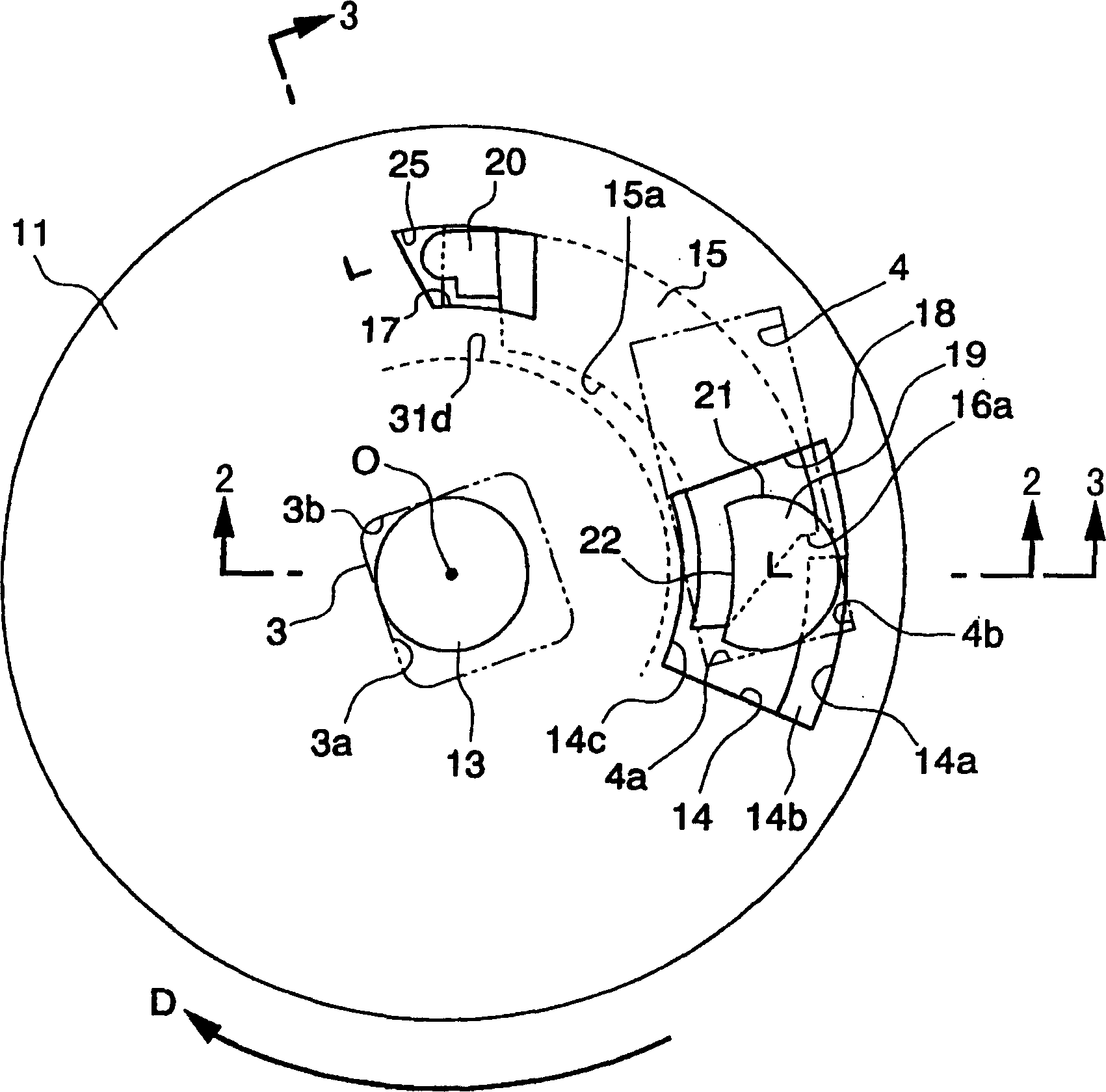
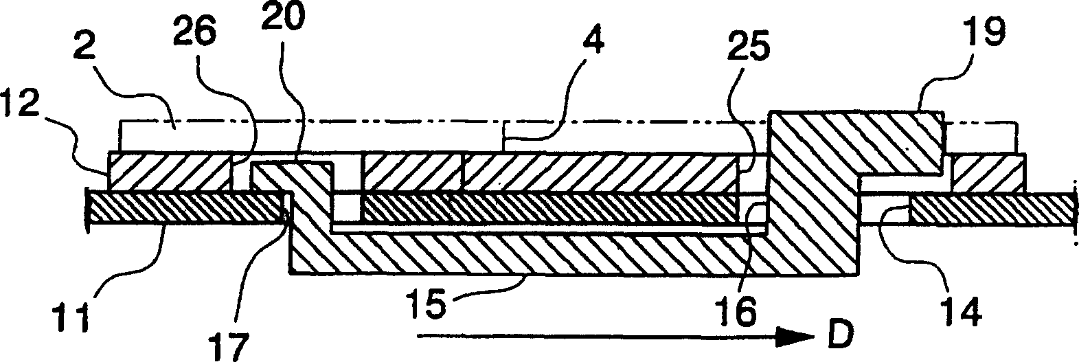
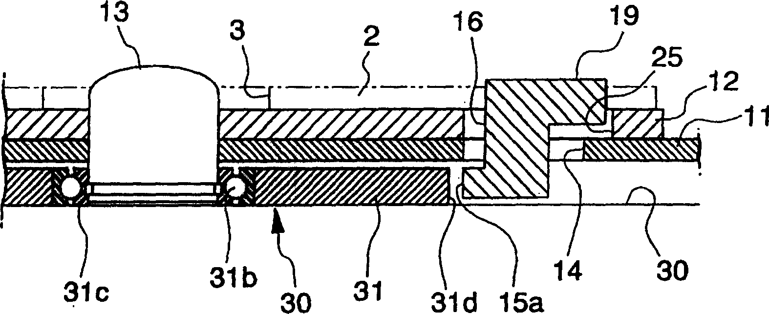
[0069] Figure 1 to Figure 3 A part of a magnetic disk drive device provided with a chucking device for a magnetic disk according to the present invention is shown. figure 1 is the plan view of the clamping device for the magnetic disk, figure 2 is along figure 1 A sectional view of the 2-2 line, image 3 is along figure 1 The 3-3 line profile.

[0070] For illustrative purposes, figure 1 removed from figure 2 The magnetic disc 12 is shown. Also in the description below for the Figure 7 , 8 The same symbols are used for the same structure of the conventional components described in , and the descriptions of these components are omitted or simplified.

[0071] exist Figure 1 to Figure 3 Among them, this disk drive device has a rotor yoke 11 composed of a ferromagnetic metal disk, which is driven to rotate in the D direction by a motor not shown,...


PUM


Abstract

The invention provides a chucking device for magnetic disk arranged so as to always accurately perform the write-in / read-out operation by realizing the front and outer supports to prevent the eccentric rotation of a recording disk. The device is provided with a nearly disk-like bearing and a driving arm 15 extended along the circumferential direction on the rear side of a rotor yoke 11 and suspended and held in the loose state at the both ends by the rotor yoke 11, and the inner circumferential surface 15a is formed on the driving arm 15 for controlling the movement to the bearing side, and a driving pin which is extended upward by feeding through a driving pin passing hole 14 of the rotor yoke 11 and inserted to a driving hole of the magnetic disk in the loose state, is formed on the front part in the rotating direction of the rotor yoke of the driving arm 15, then the chucking device for magnetic disk having such a feature is adopted that the inner circumferential surface 15a of the driving arm 15 is separated from the bearing when the rotor yoke 11 placing the magnetic disk thereon is rotated and also the driving pin is abutted on a front side edge 4a and an outer side edge 4b of the driving hole 4.

Description

technical field [0001] The invention relates to a clamping device for a magnetic disk. Background technique [0002] A disk represented by a floppy disk is usually inserted into the disk drive in the form of a cartridge. The film-shaped recording disk in the cartridge is housed in the case, and the recording disk can rotate inside the disk drive. The output or input of information is carried out through the writing / reading window with a baffle on the box body. The recording disk needs to be easy to assemble and disassemble after being housed in the case, and when writing / reading information, the recording disk needs to be accurately engaged with the rotating shaft of the disk drive device, and its rotation speed must also be accurately controlled. For this reason, disk drives are usually provided with Figure 7 and Figure 8 clamping device shown. [0003] The center of the floppy disk recording disc is equipped with a central core made of a ferromagnetic metal disc. exi...

Claims


Application Information

Patent Timeline
Patent Type & Authority Patents(China)
IPC IPC(8): G11B17/028
CPCG11B17/0282
Inventor 和宇庆朝邦
Owner ALPS ALPINE CO LTD
Why Eureka
Try Eureka