
Silicon slice conveying device

A technology for conveying devices and silicon wafers, which is applied in the direction of conveyor objects, transportation and packaging, electrical components, etc., and can solve problems such as inability to arrange silicon wafers, large volume, and secondary pollution of silicon wafers

Active Publication Date: 2015-06-24
北京京仪仪器仪表研究总院有限公司
View PDF4 Cites 0 Cited by
  • Summary
  • Abstract
  • Description
  • Claims
  • Application Information

AI Technical Summary

Problems solved by technology

Now the most used is a manipulator in the form of a three-fold arm. This type of manipulator uses three joint structures of the main arm, the auxiliary arm and the wrist to connect the manipulator fork. flakes cause secondary pollution
There is also a newly developed single-arm and single-fork manipulator. Although this manipulator can avoid the complexity of the joints, it has the same defect as the three-fold arm manipulator: they can only touch silicon wafers. Carry out simple handling operations, and the silicon wafers cannot be arranged according to the positioning grooves or positioning edges set on the silicon wafers
In this way, it is bound to increase the workload of subsequent silicon wafer processing.

Method used


Image

  • Silicon slice conveying device
  • Silicon slice conveying device
  • Silicon slice conveying device

Examples


Embodiment Construction

[0018] The present invention will be described in detail below in conjunction with the accompanying drawings and embodiments.

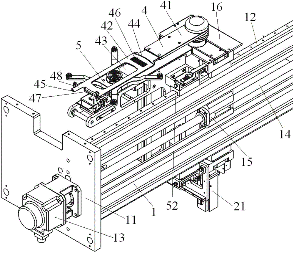
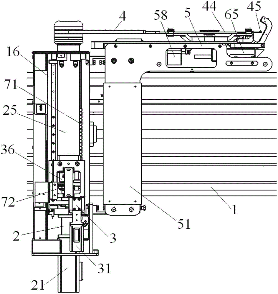
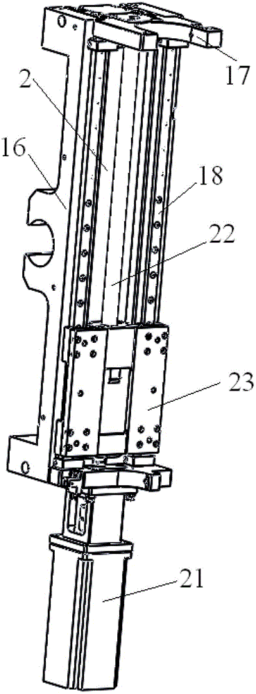
[0019] like Figure 1 ~ Figure 4 As shown, the present invention includes a horizontal drive mechanism 1, a vertical drive mechanism 2, a rotary drive mechanism 3, a manipulator fork 4, a pre-alignment mechanism 5 and a control system (not shown in the figure).

[0020] like figure 1 As shown, the horizontal driving mechanism 1 of the present invention includes a frame 11, and a horizontal slide rail 12 is respectively arranged at the upper end and the lower end of the frame 11. The middle part of one side of the frame 11 is fixedly connected with a horizontal drive motor 13, and the output end of the horizontal drive motor 13 is connected with one side of a horizontal lead screw 14, and the other side of the horizontal lead screw 14 is rotatably supported on the frame 11; The lead screw 14 is located between the two horizontal slide rails 12 and is...


PUM


Abstract

The invention relates to a silicon slice conveying device. The silicon slice conveying device is characterized by comprising a horizontal driving mechanism, a vertical driving mechanism, a rotation driving mechanism, a mechanical arm fork, a prealignment mechanism and a control system. The rotation driving mechanism and the mechanical arm fork are driven by the vertical driving mechanism to move along the vertical direction. The mechanical arm fork is driven by the rotation driving mechanism to rotate and to pick up slices. A spindle driven by a spindle motor is arranged on the front portion of the prealignment mechanism. The upper end of the spindle is connected with a sucking disc, and the lower end of the spindle is communicated with a vacuum pump. A pair of horizontal photoelectric sensors, a pair of vertical photoelectric sensors and an intelligent camera of an electric connection control system are arranged at the front end of the prealignment mechanism. The silicon slice conveying device can be directed at locating slots in silicon slices in the carrying process and read silicon slice information, and the silicon slice conveying device can be widely applied to the carrying process of various types of thinned substrates.

Description

technical field [0001] The invention relates to a mechanical handling device, in particular to a silicon wafer conveying device suitable for taking and delivering thin substrates. Background technique [0002] At present, in the semiconductor silicon wafer manufacturing industry, in order to facilitate the integration of required information on the silicon wafer, a positioning groove is often set on the edge of the circular silicon wafer to indicate the direction of the silicon wafer, and the fixed position relative to the positioning groove is engraved. There is corresponding information of the silicon chip (can be digital symbols, one-dimensional barcode, two-dimensional code, etc.), which is convenient for repeated positioning and information reading of multiple integrated circuit processing. Moreover, due to the influence of the processing environment and the assembly process, it is usually necessary to repeatedly transfer silicon wafers in various process equipment at h...

Claims


Application Information

Patent Timeline
Patent Type & Authority Patents(China)
IPC IPC(8): H01L21/677H01L21/68H01L21/67
Inventor 陈百捷姚广军刘影蒋俊海刘学辉赵力行
Owner 北京京仪仪器仪表研究总院有限公司
Learn More