Rotary joint suitable for high-speed-change rotation and frequent start-stop working conditions
What is Al technical title?
Al technical title is built by PatSnap Al team. It summarizes the technical point description of the patent document.
A technology with frequent start and stop and working conditions, applied in the direction of pipes/pipe joints/fittings, adjustable connections, passing elements, etc., which can solve the problems of rotating mandrel rotation obstruction, difficult disassembly and assembly, and unfavorable use.
Active Publication Date: 2021-12-07
SHANDONG MINGHUI IND TECH CO LTD
View PDF0 Cites 0 Cited by
Summary
Abstract
Description
Claims
Application Information
AI Technical Summary
This helps you quickly interpret patents by identifying the three key elements:
Problems solved by technology
Method used
Benefits of technology
Problems solved by technology
[0004]
The purpose of the embodiments of the present invention is to provide a rotary joint suitable for high-speed variable rotation and frequent start-stop conditions, aiming at solving the problem that most current rotary joints are fixed by screws, which are difficult to disassemble and may be fixed after being fixed. It will hinder the rotation of the rotating mandrel, which is not conducive to the use of the problem
Method used
Image
Click on the blue label to locate the original text in one second.
Reading with bidirectional positioning of images and text.
Examples
Embodiment Construction
[0035] In order to make the object, technical solution and advantages of the present invention clearer, the present invention will be further described in detail below in conjunction with the accompanying drawings and embodiments. It should be understood that the specific embodiments described here are only used to explain the present invention, not to limit the present invention.
[0036] The specific implementation of the present invention will be described in detail below in conjunction with specific embodiments.
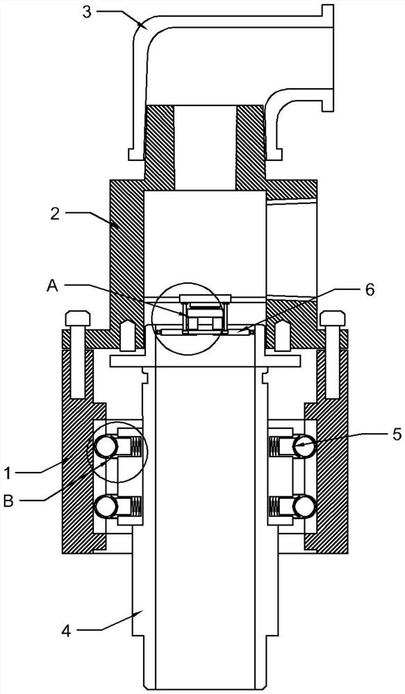
[0037] Such as figure 1 As shown, in the embodiment of the present invention, the rotary joint suitable for high variable speed rotation and frequent start and stop conditions includes:
[0038] A fixed end housing 1, a channel pipe 2 is connected to one side of the fixed end housing 1, and an elbow pipe 3 is connected to one side of the channel pipe 2;
[0039] The rotating mandrel 4 is arranged inside the fixed end housing 1, and a rotating connection assembl...
PUM
Abstract
The invention is suitable for the field of rotary joints, and provides a rotary joint suitable for high-speed-change rotation and frequent start-stop working conditions, the rotary joint suitable for high-speed-change rotation and frequent start-stop working conditions comprises a fixed end shell, a rotary core shaft and a fastening assembly, one side of the fixed end shell is connected with a channel pipe, and one side of the channel pipe is connected with an elbow pipe; the rotary core shaft is arranged in the fixed end shell, and a rotary connecting assembly is arranged between the rotary core shaft and the fixed end shell; and the fastening assembly is arranged in the channel pipe. When the rotary joint suitable for the high-speed-change rotation and frequent start-stop working conditions is used, the rotary core shaft is arranged in the fixed end shell and the channel pipe, at the moment, the fixed end shell and the rotary core shaft are preliminarily connected through the rotary connecting assembly, and then the fastening assembly is driven to operate; and thus the fastening assembly connects the rotary core shaft with the channel pipe, so that the rotary core shaft is connected and fixed, and the rotation of the rotary core shaft is not hindered.
Description
technical field [0001] The invention belongs to the field of rotary joints, and in particular relates to a rotary joint suitable for high variable speed rotation and frequent start-stop working conditions. Background technique [0002] Rotary joints refer to pipeline connection devices, and the connected pipelines can be rotated relative to each other, and can be used to transmit various media such as gas, liquid and oil. The rotary joint is a closed rotary connector that rotates 360° to convey the medium. The application fields of the rotary joint cover almost all processing and manufacturing industries, such as: metallurgy, machine tools, power generation, petroleum, rubber, plastics, textiles, printing and dyeing, pharmaceuticals, cigarettes, papermaking , food, feed processing, etc.; rotary joints can be divided into: hydraulic rotary joints, high-pressure rotary joints, multi-channel rotary joints, high-speed rotary joints, high-temperature rotary joints, single-channel...
Claims
Application Information
Patent Timeline
Application Date:The date an application was filed.
Publication Date:The date a patent or application was officially published.
First Publication Date:The earliest publication date of a patent with the same application number.
Issue Date:Publication date of the patent grant document.
PCT Entry Date:The Entry date of PCT National Phase.
Estimated Expiry Date:The statutory expiry date of a patent right according to the Patent Law, and it is the longest term of protection that the patent right can achieve without the termination of the patent right due to other reasons(Term extension factor has been taken into account ).
Invalid Date:Actual expiry date is based on effective date or publication date of legal transaction data of invalid patent.